6. FY06 PROGRESS IN ADVANCED COMPUTATIONS
by Kwok Ko
Appendix B Self-Evaluation FY2006
Return to Table of
Contents
In FY06, the codes
T3P
(wakefields) and Track3P
(multipacting) with extensive benchmarking, joined Omega3P
(eigensolver) and S3P
(scattering matrix) to form a comprehensive suite of
parallel electromagnetic codes developed under SciDAC.
Close to maturity is the parallel 2D PIC code Pic2P
for rf gun simulation and under development is a
parallel 3D code Gun3P
for beam formation and transport in sheet beam
klystrons. Using these codes, a majority of ACD’s
efforts in the past year has turned to accelerator
applications such as the ILC, PEP-II, Advanced
Accelerator Concepts and the LCLS. Highlights from these
simulations follow.
Transients and Cavity Deformations in the ILC TDR Cavity
The temporal electromagnetic field behavior in the ILC
baseline TDR (TESLA) cavity due to a beam transit was
simulated with T3P
to obtain useful information on the transients in the
cavity and the 3D effects from the couplers (input and HOM) on the short range wakefields. Figure 1 shows two
snapshots in time of the magnetic fields (image current)
on the cavity wall induced by the transiting beam: the
first set of pictures from before the beam enters the
cavity and the second set after the beam has passed.
Performed on NERSC’s Seaborg, the T3P
simulation parameters were: 1.75M quadratic elements
(10M DOFs) requiring 173 GB on 1024 processors and 47
minute per ns of beam travel.
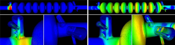
Figure 1: Snapshots of
T3P
magnetic field contours on the wall surface of the TDR
cavity and couplers before beam enters main cavity (Left
set) and after exiting output end beampipe (Right set).
Each of the two dipole bands in the TDR cavity consists
of 9 pairs of modes as the mode degeneracy is split by
the input and HOM couplers. Figure 2 shows the
comparison between the Omega3P
results from the ideal cavity and the measurement of 8
cavities in a DESY cryomodule for the sixth pair in the
second band. It is observed that for the measured data:
(1) the splitting of the mode pair is larger; (2) the
mode pair is mostly shifted to lower frequencies; and
(3) their Qe’s are scattered towards the high side. The
Qe increase would be problematic if they exceed the beam
stability limit. The differences between simulation and
measurement can be attributed to cavity deformations. An
effort has begun to determine the cavity shape by
solving an inverse problem using the TESLA data as input
parameters.
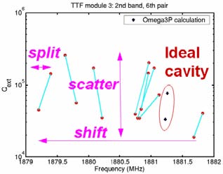
Figure 2: Comparison between ideal cavity results from
Omega3P
and measurements from 8 different TESLA cavities in an
actual cryomodule, showing differences in mode
splitting, mode frequencies and damping.
Mode Damping in the ILC Low-loss Cavity and the 3.9 GHz
Crab Cavity
The Low-Loss cavity design (Figure 3) is being
considered as a possible upgrade to the baseline TDR
cavity for the ILC main linac. Based on a different cell
shape, it has 20% lower cryogenic loss plus higher
gradient (via a smaller cavity iris) over the TESLA
design. Additionally, the end pipes where the couplers
are located are larger than the cavity iris to allow for
adequate coupling to the input coupler plus more
effective HOM damping. Using the HOM coupler from the
TESLA cavity directly,
Omega3P
analysis found that the first mode in the third dipole
band does not meet the beam stability requirement of Qe
< 105.
A high fidelity mesh consisting of 0.53M quadratic
elements (3.5M DOFs) was used to model the cavity. This
provides sufficient resolution for modifying the end
groups to improve the HOM damping. By adjusting the
end-pipe radius, the HOM coupler azimuthal location, and
the loop shape and configuration (Figure 3 colored
inserts), the Qe of the dangerous third band mode was
reduced to below the stability threshold. The
Omega3P
simulations were performed on NERSC’s Seaborg with a
direct solver, requiring 300 GB memory on 512 processors
and one hour of runtime per dipole band. Comparison
between original and new damping results is shown in
Figure 4.
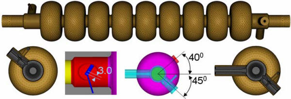
Figure 3: Mesh models of the LL cavity including the end
groups and with the modifications of the HOM loop
orientation and the coupler location shown in colored
inserts.
Figure 4: Qe versus frequency for the LL cavity with
TESLA HOM coupler (in blue) and SLAC’s improved design
(in red).
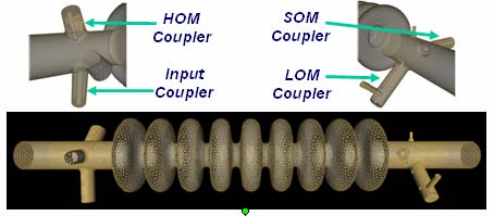
Figure 5: Mesh model of the FNAL design of the ILC crab
cavity showing input, LOM, SOM and HOM couplers.
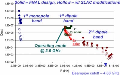
Figure 6: Mode damping improvements in the ILC crab
cavity after 1st
SLAC modifications.
The crab cavity employs the first deflecting mode to
rotate the beam bunches to achieve higher luminosity at
the ILC interaction point. The existing FNAL design has
been simulated and preliminary modifications have been
made to the computational model (Figure 5) to provide
improved damping results (Figure 6).
Multipacting and Notch Filter Sensitivity in the ILC
ICHIRO Cavity
Researchers at KEK are devoting a large effort to high
gradient cavity R&D for the ILC with the focus on the
ICHIRO cavity which evolved from the LL cavity design.
In single cell tests, the ICHIRO design established a
record gradient of 54 MV/m while 9-cell ICHIRO cavities
(Figure 7) are having difficulties reaching gradients
greater than 30 MV/m. The ICHIRO cavity differs from the
LL design in the enlarged end-tube at the input end.
Using
Track3P
multipacting activity in the transition from the
enlarged end-tube to the beam pipe was revealed from
simulation (Figure
7). The calculated MP levels are found to be in good
agreement with X-ray barriers observed in the experiment
(Figure 8). Work is underway to redesign the cavity to
circumvent this problem.
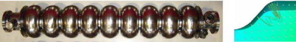
Figure 7: (Left) 9-cell ICHIRO cavity prototype under
high power tests at KEK with enlarged end-tube shown on
the input end to the left, (Right) MP trajectory in the
transition from enlarged end-tube to beam pipe.
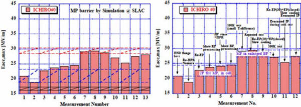
Figure 8: (Left) MP barriers in 9-cell ICHIRO cavity
calculated with Track3P, (Right) MP barriers measured on
ICHIRO prototype (K. Saito, KEK).
The notch filter in the TESLA HOM coupler is designed to
reject the fundamental mode power while allowing damping
of all HOMs. To study its sensitivity and detuning
effect due to change in notch gap dimensions, two
calculations were carried out. First the tuning curves
of the HOM coupler for three different notch gap
dimensions were computed with
S3P
to find the response around the fundamental mode
frequency of 1.3 GHz (Figure 9) and a sensitivity of
0.11 MHz per micron was obtained. Next, the fundamental
mode was computed for the cavity complete with HOM
couplers set at the three different notch gap
dimensions. A comparison of the fields in the HOM
couplers from the fundamental mode in the three cases is
shown in the table in Figure 9. While the notch gap
fields vary little in all cases, the Qe of the mode is
reduced by orders of magnitude when the notch filter is
tuned far off the notch frequency at 1.3 GHz. This could
lead to large amounts of power flowing through the
feed-through and could result in excessive heating if
proper cooling is not factored into the design.
Figure 9: (Left) Detailed mesh in the ICHIRO HOM coupler
showing mesh density in the notch gap and near the
antenna tip, (Middle) tuning curves of HOM coupler with
three different notch gaps near 1.3 GHz, (Right) Field
values in the notch gap and at the antenna tip for three
different notch gap dimensions and the corresponding Qe.
Multipacting
Studies for the ILC TTF III Input Coupler
Track3P simulations are being performed to investigate
the effect of multipacting on the processing of the ILC
TTF III input coupler. A model of the coupler is shown
in Figure 9 (Left). Initial studies have been focusing
on the region around the cold bellows as depicted in
light blue in the model. The operating power level is
between 300 and 400 kW. Simulations results reveal
multipacting activities near 360 kW power level with
multipacting particles impacting the coax outer wall but
none within the bellows. The distribution of impact
particles shown in Figure 9 (Middle) reflects the
electric field profile along the coax which has a
standing wave component on the upstream side of the
bellows but remains a purely traveling wave on the
downstream side. A typical particle trajectory on the
upstream side is displayed in Figure 9 (Right) and it
represents a fifth-order multipacting. Work is
continuing to determine if the multipacting barrier
persists beyond 20 impacts and the simulation will be
extended to include the entire coupler geometry.  Figure 9: (Left) Model of the TTF III input coupler,
(Middle) impacts of multipacting particles along the
outer wall of coax, (Right) a typical particle
trajectory with impacts close to the cold bellows on the
upstream side.
Trapped Modes in ILC Multicavity Structures
First studied at DESY, the superstructure design for the
ILC combines two or more cavities through weakly coupled
beam pipes into a single unit. The goal is to reduce the
number of input couplers and increase the packing
fraction which reduces the linac length. One concern
with superstructures is the presence of trapped modes
between cavities. Figure 10 shows a two-cavity
superstructure model and a HOM trapped between the
cavities as computed by Omega3P. The ILC GDE has
expressed strong interest in computing the wake fields
for an ILC RF unit consisting of 3 cryomodules with 8
TDR cavities each. As a first step, a four-cavity
structure which is relevant to KEK’s STF cryomodule is
being modelled. The simulation parameters on NLCF’s
Phoenix are: 2.52M quadratic elements (15.2 M DOFs)
requiring 280 GB on 1000 CPUs and 23 hours of runtime
for 2 eigenmodes. The solution method used was Second
Order Arnoldi with restarted GMRES and multilevel
preconditioner. One of the modes with high fields in
between the cavities is shown in Figure 11. Rough
estimates of the computational requirements for
modelling the entire ILC RF unit are 20-30 M quadratic
elements (100M – 200M DOFs) and several thousand modes.
This challenging simulation will require petascale
computing resources and advances in scalable eigensolver
algorithms as well as parallel refinement techniques.
Efforts in these two computational science research
areas are in progress under SciDAC.

Figure 10: Two-cavity superstructure model and a trapped
mode found by
Omega3P.

Figure 11: One
Omega3P
computed HOM in the ILC 4-cavity structure with strong
fields between cavities.
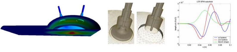
Broadband Impedance of PEP-II LER BPM
During PEP-II operation some BPMs in the LER lost the
buttons due to poor thermal contact. There was a request
to find out through simulation the effect of the missing
buttons on the ring’s broad band impedance. This problem
is very difficult for structured grid codes like
MAFIA
to solve accurately because of the elliptical vacuum
chamber and the fine details in the BPM. Figure 12 shows
a high fidelity model of the geometry for the vacuum
chamber as well as the BPM with and without buttons.
Using
T3P
on NERSC’s Seaborg, the mesh resolution was increased
till the wakefields converged. The results for the
short-range wakefields are shown in Fig 12 which
compares the case with buttons to that without buttons
indicating the difference is not significant. The PEP-II
has since operated normally even with some missing
buttons in a number of LER BPMs.
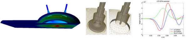
Figure 12: (Left) Upper-half model of the PEP-II LER
vacuum chamber with two BPMs and showing the beam down
the axis, (Middle) Mesh of the BPM with and without
button, (Right) Comparison of short-range wakefields in
the two cases.
Wakefields in the MIT Photon-Band-Gap (PBG) Structure
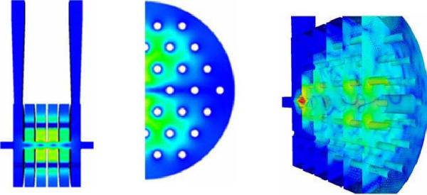
Figure 13: (Left) A dipole mode at 23 GHz computed by
Omega3P
with Qe = 131, (Right) wakefields generated by a beam
using
T3P.
Absorbing boundaries are imposed at the outer wall in
both cases.
ACD is collaborating with MIT and STAR, Inc on a SBIR
project to advance the R&D on the Photon-Band-Gap (PBG)
structure as a promising Advanced Accelerator Concept.
The PBG is, by design, a single mode structure in which
all HOMs are not confined and therefore can escape from
the structure once generated by the beam. MIT has
fabricated a 17 GHz PBG structure which demonstrated
that it can provide 35 MV/m accelerating field-gradient
in beam tests. The role of simulation is to verify the
effectiveness of the PBG concept in damping HOMs. For
the MIT 17 GHz structure, both time and frequency domain
simulations were carried out. Figure 13 (Left) shows one
HOM computed with
Omega3P
that has a Qe of 131 so is heavily damped. The
wakefields due to a transit beam modeled with
T3P
is shown in Figure 13 (Right) where no high fields
inside the structure were seen after some time. In both
Omega3P
and
T3P
simulations absorbing boundaries were imposed at the
outer wall of the PBG structure.
RF Gun Simulation for the LCLS
In the past year, ACD has devoted a significant effort
to the development of a parallel particle-incell
capability which is based on conformal grids and
higher-order finite elements for superior geometry
representation and higher field accuracy. There is
strong interest in such a code from the rf gun community
because of the growing need for high brightness, low
emittance beams in next generation FELs and light
sources. The initial focus is on the 2D code,
Pic2P,
with the LCLS rf gun as the target application. To our
knowledge,
Pic2P
is the first successful implementation of
self-consistent particle-field interaction on an
unstructured grid. Based on first principles, the code
contains all pertinent physics effects such as space
charge, retardation and wakefields. Figure 14 (left)
shows the highly unstructured mesh of the LCLS rf gun
with mesh densities concentrated along the beam path.
The particle bunch as accelerated by the driven cavity
mode and the scattered fields generated by the beam in
its interaction with the gun cavity are shown in Figure
14 (middle) and Figure 14 (right) respectively, This is
the first time that the wakefields in the LCLS rf gun
have been calculated accurately. The effect, though, is
relatively small, accounting for about a 6% change in
the transverse emittance. The comparison of the
normalized RMS transverse emittance between
Pic2P, MAFIA
and PARMELA
for different bunch charge is summarized in Figure 15
(left). There is excellent agreement between
Pic2P
and
MAFIA
although
Pic2P
requires far less computational resources to reach the
same convergence. Figure 15 (right) shows the parallel
speedup presently achieved by
Pic2P
and the good scalability makes it viable to use the code
as a design tool as the computing time can be reduced to
the same order as PARMELA’s
while providing all the correct physics as a PIC code
can. Work has begun on the 3D version (PIC3P)
which will be an invaluable tool for commissioning the LCLS gun.
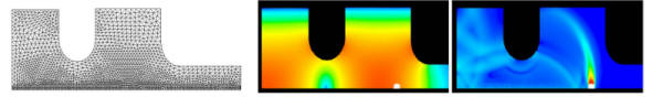 Figure 14: (left) Mesh of the LCLS rf gun, (middle)
Particle bunch accelerated by operating mode as modeled
by Pic2P, (right) scattered fields generated by
the beam in its interaction with the RF gun cavity.
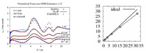
Figure 15: (left) Comparison of the normalized
transverse RMS emittance for different bunch charges
between MAFIA, Pic2P and
PARMELA,
(right) parallel speedup of current
implementation of Pic2P.
|