|
|
|
||
|
|
|
||
|
|
5.A FY06 PROGRESS: ACCELERATOR TECHNOLOGY RESEARCH
DEPARTMENT
|
| Structure Type | Simple π Mode |
| Cell Number | 11 |
| Aperture 2a | 60 mm |
| Q | 29700 |
| Shunt impedance r | 34.3 MΩ/m |
| E0 (8.6 MW input) | 15.2 MV/m |
Table 2 Parameters of 4.3 m TW structure
| Structure Type | TW 3π/4 Mode |
| Cell Number | 50 |
| Aperture 2a | 46 mm |
| Attenuation τ | 0.98 |
| Q | 24842 - 21676 |
| Group velocity Vg/c | 0.62% – 0.14% |
| Shunt impedance r | 48.60 – 39.45 MΩ/m |
| Filling time Tf | 5.3 μs |
| Power Dissipation | 8.2 kW/m |
| E0 (10 MW input) | 8.5 MV/m |
The simple π mode SW structure with 11 cells is designed for high gradient (15 MV/m) positron capturing. The advantages are more effective cooling, higher shunt impedance with larger aperture (60 mm), lower rf pulse heating, apparent simplicity and cost saving. The mode and amplitude stability for this type of structure has been calculated theoretically to be feasible.
In order to optimize the rf efficiency, the “phase advance per cell” has been used as a knob for designing large aperture, constant gradient 4.3 m TW structures. The advantages are lower pulse heating, easy installation for long solenoids, no need for rf reflection protection (circulators), apparent simplicity and cost saving.
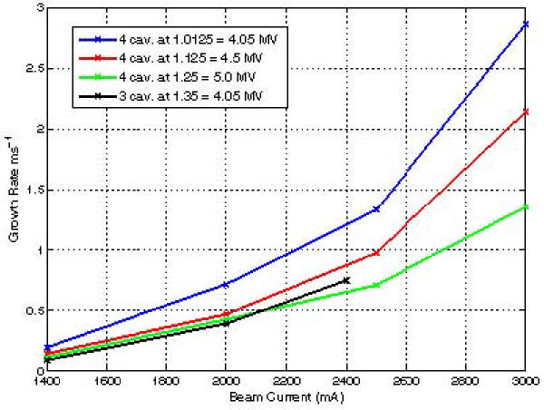
Some extensive PARMELA simulations have been conducted for the beam dynamics using various accelerating gradients and structure combination.
2). L-Band 5-cell SW test accelerator section for the positron capture structure
In order to gain fabrication experience and to make high power tests at full gradient and pulse length with an existing 5 MW peak power L-band klystron, a 5-cell L-band test structure was designed with a coupler cell at one end and all necessary features for a positron capture section. Due to the low priorities in the machine shops, the structure fabrication schedule has been much delayed. Hopefully, this will be completed by the end of 2006 and the test can be started in the early 2007.
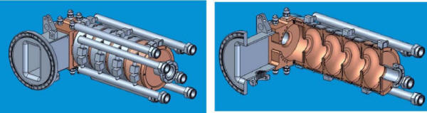
Figure 2. A 5-cell L-band SW accelerator section for the positron capturing.
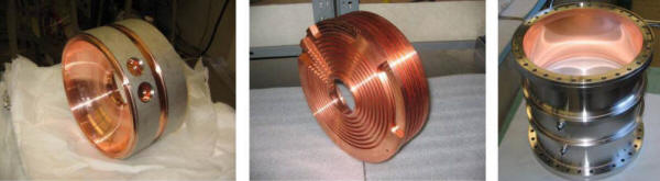
Figure 3. Some of the subassemblies for the 5-cell SW structure: a completed unit cell (left), a half cell to be brazed on the input coupler (middle), L-band rf window (right).
3). Three S-Band BPMs have been tested for the ILC main linac beam diagnostics. The measurements showed the TM11 mode working frequencies were accurate with 2856 + 1-3 MHz and two orientations were balanced with frequency difference Δ|fx-fy|<0.75 MHz. The loaded QL value was close to the designed value with 420 – 550. The cross coupling between x/y pick-ups was better than -40db.
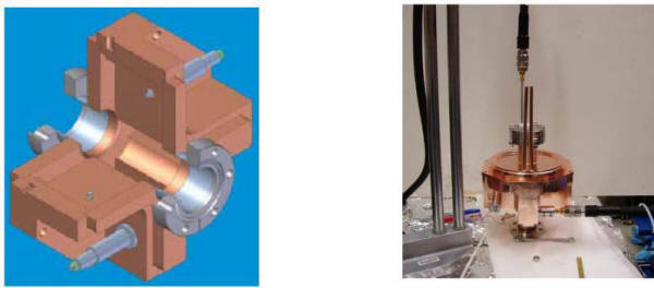
Figure 4. S-Band BPM for the ILC main linac: the cutaway view (left) and microwave measurement set-up (right).
4). Rf design of a Higher Order Mode (HOM) polarized rf gun for the ILC
The ILC requires a polarized electron beam. The ILC injector system can be simplified and made more efficient if a GaAs-type cathode can be combined with a low emittance rf gun. Compared with existing rf guns, this type of cathode is known to be extremely sensitive to vacuum, contaminations, and back bombardment by electrons and ions. Careful studies have been made of a new rf design for an L-band normal conducting (NC) rf gun for the ILC polarized electron source. This design incorporates a higher order mode (HOM) structure, with much-improved conductance for vacuum pumping on the cathode. Computer simulations have been used to optimize the rf parameters with three principal goals: first to minimize the required rf power; second to reduce the peak surface field relative to the field at the cathode in order to suppress field-emitted electron bombardment, third to minimize the maximum surface magnetic field for reduction of pulse heating and ease of cooling. The beam properties have also been simulated initially using PARMELA.
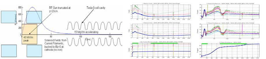
Figure 5. Layout of the polarized rf gun system (left) and beam dynamics simulation (right).
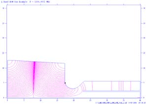
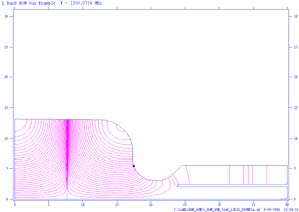
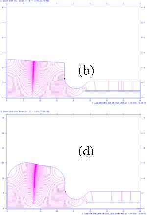
Figure 6. Design examples for an HOM rf gun: (a) with an output iris radius of 2.4 mm;
(b) with an output iris radius of 3.4 mm; (c) with a rounding radius of 5 cm on the outer cell wall at the output end; and (d) with an additional rounding radius of 6 cm.
Accelerator structures work for the LCLS began with the 2004 LCLS Injector RF Technical Review. 1). Tuning and characterization of the LCLS rf gun
The rf performance of the first LCLS rf gun has been thoroughly studied including the frequencies of the 0-mode and π-mode, quality factor as a function of the cathode tightening torques, the electrical field distribution along the gun axis, coupling coefficient and so on. The tuning was done by machining a tuning ring in the cathode cell based on careful microwave measurements and calculations.
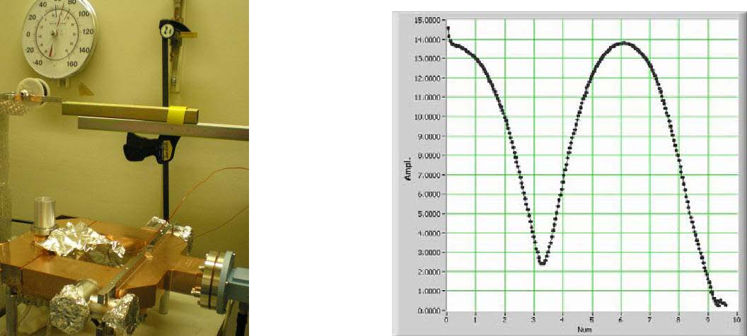
Figures 7. A bead drop microwave measurement set-up for the electrical field distribution (left) and a plot showing a perfect balanced field in cathode cell and coupling cell (right).
By using bead pull technology and precise frequency measurements for various cathode curvatures, complete tuning curves – the ratio of the fields in cathode cell and coupling cell as a function of mode spacing between the 0-mode and π-mode frequencies - as shown in the right plot in Figure 8 - have been obtained and studied. The round red dot is the perfect working point in the present and future reference for cathode replacement. This work not only contributed to the LCLS project for producing a superior quality rf gun, it also gained some important knowledge for its operation as well as the design of the next generation of the LCLS rf gun.
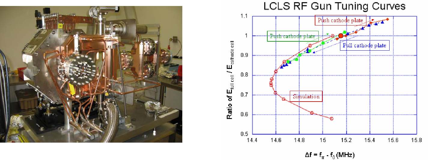
Figure 8. The final assembly of the first LCLS RF gun after microwave tuning, characterization and test probes calibration (left) and the tuning curves (right).
2). In addition to measurement, retuning and evaluation of two 9.5 ft S-band accelerator sections for the new LCLS beam line, two candidates were selected for booster sections from six 10-foot S-band accelerator sections. The front ends were modified with new double input waveguides and 5 new cells. The tuning and characterization are complete. They are now baking and will soon be ready for installation. A deflector section was also tuned for the beam length measurement.
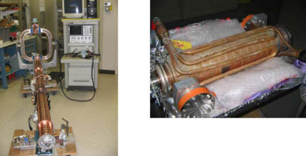
Figure 9. Microwave measurement set-up for an S-band TW booster section (left) and a deflector for the beam length measurements for the LCLS (right).
1). Wire-based structure experimental method
Progress continues to be made in wire measurement for accelerator studies. This method can quickly and inexpensively analyze the wakefield suppression properties of accelerator structures. An improved control program has been developed to move a brass wire using microstepping motors and data acquisition. Also, we are still analyzing the recorded S-parameters for interpreting them to deduce the impedances of the monopole band as well as the impedance of higher dipole mode bands.
2). MicroLinac
Work continues on the MicroLinac, which is a small, standing wave (SW) linac. It is intended as a low-cost radiography source with dosage larger than 100 Ci. This linac could be used in place of radioactive sources, which can potentially be used for “dirty bombs.” The preliminary operation showed too much of the unwanted rf phase drift due to the rf power transfer, leading to the beam energy reduction and low capture efficiency. Now, design studies are under way for an alternative traveling wave structure.
During this fiscal year a dedicated high-gradient program was initiated at SLAC. This program is part of the new US collaborative initiative on high gradient research. The purpose of this collaboration is to perform research to determine the gradient potential of normal-conducting, rfpowered particle beam accelerators, and to develop the necessary accelerator technology to achieve those high gradients. Harnessing the momentum of the concluded NLC/JLC development programs and working in conjunction with the ongoing CLIC studies, the collaboration will explore the possibility of pushing the useable acceleration gradient from the 65 MV/m reliably achieved in NLC structures up towards 180 MV/m or higher. Advancing the state-of-the-art in this area is essential to the realization of a post-ILC, multi-TeV linear collider using two-beam rf power generation.
This research and development effort includes studying the rf breakdown phenomenon itself, both theoretically and experimentally. This effort aims to establish a better understanding of the frequency scaling of the limiting gradient, as well as its dependence on material, surface preparation, structure design, pulsed heating, etc. It will explore the high gradient barriers due to choices made in linear collider programs to date. The experimental side of this effort will entail the upgrade of test facilities and the development of new high-power rf sources specifically designed for high gradient testing. The final goal is to produce and successfully test at very high gradient an accelerator structure suitable for use in a multi-TeV two-beam linear collider.
The high-gradient research initiative began with a two-day workshop in July 2005, which was organized by SLAC. The workshop spawned a nationwide collaboration consisting of several participating institutions, including universities and government laboratories, each of which submitted one or more proposals for work related to the goals of this initiative. These participants all have histories of contributions to the fields of accelerator design and/or high power rf R&D. Each institution brings its own capabilities, facilities and academic/scientific missions to the service of the collaboration and will be funded for participation through their normal DOE grants. These institutions form the initial collaboration; however, the make up of the collaboration may change based on each institution’s funding and goals.
After the initial meeting, several activities under the leadership of SLAC scientists continued to strengthen this collaboration
a. On September 9, 2005, S. Tantawi gave a talk at LBNL and discussed their planned studies.
b. Second collaboration meeting at the University of Maryland, November 18, 2005.
c. The 2006 Advanced Accelerator Concepts workshop had a working group on High Gradient RF Research chaired by S. Tantawi (SLAC) and co-chaired by V. Dolgashev (SLAC).
SLAC hosts this collaboration. Its experimental facilities will be available to collaborators for experiments supported through this collaboration. The program at SLAC will have three principal elements:
1) Enhancement of the experimental facilities,
2)
SLAC’s experimental program, and
3) SLAC’s
theoretical program.
Rf breakdown studies are still in their infancy. Very little is known either about the theory of surface breakdown at microwave frequencies or about the effect of geometries and the response of simple materials, let alone alloys and composites. The initial program is characterized by intensive experimental efforts. This program has to address the basic physics of breakdown phenomena. Because of its exploratory nature, a large number of experiments addressing different aspects of geometrical change and material variations are needed. Hence, priorities have to be given to establish experimental facilities capable of operating with a high enough repetition rate. Also, as recent experiments show, the frequency scaling of rf breakdown is not well understood. Therefore, it is necessary to carry out experiments at different frequencies. To do this, a variety of high frequency rf sources is required, some of which will need to be developed. In addition to studying breakdown phenomena in existing accelerating structures, it is necessary to have experimental facilities to test novel structures.
Generally speaking, any high gradient rf structure reaches its limits after a period of high power processing. The nature of this processing is an open question. However, it is known that most structures more than double their initial gradient after processing. Also, the initial gradient that the structure can handle is poorly correlated with the final gradient after processing. This initial gradient correlates well with the surface processing and machining of the surface, while the final gradient is usually a function of material and geometry. Therefore, the processing time depends on the preparation and surface treatment. Although a system where this processing time goes to zero would be ideal, the potential for reduced or no processing time for a particular geometry or a material can not be ascertained without processing.
In any high vacuum system, a typical installation procedure will take about 3 days to complete. At X-band, the processing of copper structures typically takes about 3 days at 60 Hz, with close to 1,000 breakdowns. Refractory metals, on the other hand, take close to 4 weeks, with close to 100,000 breakdowns. Thus, an experimental program aimed at exploring the problem in a systematic way requires several test stands and the ability to change and test structures relatively quickly. The test stands need to be able to run at high repetition rate (~60 Hz).
At the moment, the only place in the US capable of doing tests at frequencies at S-band or above is SLAC. Ideally, SLAC should serve as the primary experimental site for the collaboration. At X-band, SLAC has three stations at the NLCTA and one station at the Test Lab capable of producing uncompressed pulses of ~80 MW, and each of these stations has an associated pulse compressor. There are an additional two stations, each capable of producing up to 50 MW, but with no associated pulse compressor. The capabilities of these stations vary, and they are not all capable of supporting all types of experiments. In effect, there are four useful experimental stations. Even if they are all dedicated to this program (at the moment not one is dedicated to this program), and assuming an average of 4 weeks/experiment for processing and characterization and a running time of 40 weeks/year, only 40 experiments would be completed per year, barely enough to do all the systematic studies needed. The rate of 40 weeks of running time and 4 weeks per experiment assumes that these stations are all equipped with data acquisition systems and monitors and that there are enough scientists and staff to service the stations and to conduct the experiments. Clearly this is not currently the case. As things stand, during the NLC development time, the NLCTA was capable of supporting about 10 experiments/year. The Test Lab supported about 3 experiments/year. Hence, the first order of business is to enhance the capabilities of these test stands:
The programs/users that these stands will serve, for the first year, are:
A. Gyrotron Development High power rf sources at high frequency, 11.4GHz < f < 30GHz, are not available. These are needed to study one of the most fundamental issues in high gradient research, frequency scaling of breakdown limits. At these high frequencies, a klystron is not the device of choice. Gyrotrons are more suitable, because they are fast-wave devices, in which microwave power is produced in the circuits with sizes on the order of a wavelength and above. Gyrotron oscillators and amplifiers have a long history of success at frequencies from 8-10 GHz up to 100-200 GHz. Usually, gyrotron oscillators are simply called gyrotrons, while gyroklystrons are amplifier forms of these devices. Fundamentally, the development of amplifiers is much more difficult than the development of oscillators. In accelerator applications, amplifiers are traditionally needed for two reasons: synchronizing several devices and manipulating phase for a pulse compression system. However, for high gradient studies of single structures, raw power is all that is needed. Also, developments in active pulse compression make it possible to compress an oscillator signal.
Under the US High Gradient Collaboration, development was proposed of a gyrotron oscillator at SLAC in collaboration with other institutes. The oscillator comprises the following elements:
1- A modulator.
I. The modulator already exists at SLAC.
2- A magnet, which can be either a superconducting
magnet for millimeter-wave radiation or water-cooled
solenoid for frequencies up to 20-30 GHz,
3- A
magnetron injection gun (MIG)
I. The MIG can be electrically designed as a collaboration between SLAC, the University of Maryland, MIT and CPI
II. The mechanical design of the MIG could be done at SLAC.
4- Two microwave circuits to be installed on top of the gun, one at 30 GHz and the other at ~22 GHz.
I. The microwave circuit design can be done in collaboration between SLAC, University of Maryland, MIT, CCR and CPI II. Manufacturing could be done at SLAC or at outside shops. The necessary machining is not demanding..
5- Active pulse compressors for the two frequencies. These can be developed within SLAC.
The system can be installed near the ASTA bunker and operated there for high gradient studies at high frequency. This is the shortest route to providing a workhorse for high gradient studies at high frequencies, which could serve the worldwide research community. It is also the most economical route to designing and building these devices
B. Active Pulse Compression Active pulse compression at high frequencies (11.4 GHz < f < 91 GHz) can be readily achieved with the use of laser triggered bulk effect semiconductor switches. With the advances made in this field during recent years, one can project an inexpensive active pulse compression system at 30 GHz, which can be powered by either an oscillator or an amplifier. The development of such a system would be the shortest path to an operational test stand at 30 GHz. It could be used with CLIC’s CTF-3 facility to compress the output of the extraction linacs. Fast changes of the output of these linacs are not easily attained, and a pulse compressor that can work without a phase-flip is the key device to make a useful test stand at CERN. Also building a gyrotron oscillator is far easier than building a gyroklystron amplifier, and, as stated above, this will provide the needed compression system for such an oscillator. Such a system has been designed and is now under construction.
SLAC’s Experimental Program
The program is aimed at:
1) The study of the basic physics of rf breakdown, and
2) Studying and testing novel accelerator structures, including CERN and KEK structures.
Basic Physics Experimental Studies
There are three basic vehicles for these studies:
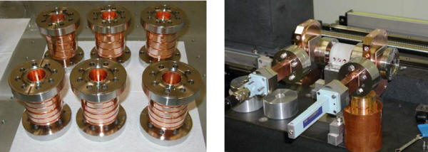
Figure 1. a) “single-cell” traveling-wave and standing-wave test accelerator structures and b) a “single-cell” structure with demountable low-field couplers attached.
The single-cell, traveling-wave accelerator structures employ a new concept recently developed at SLAC. In these structures, a single cell which is a true representative of a cell of a long accelerator structure, is inserted between matching geometries that mimic the response of a long accelerator structure. This matching geometry has much lower fields though than the accelerator cell. In this manner, one retains as much as possible the elements of a real accelerator structure while testing a structure that is much simpler and is amenable to simulation and modeling.
Demountable couplers were added to these structures. The concept was invented at SLAC and this type of coupler has been proven to be reliable and tolerant of high power operations. This greatly reduces the cost of testing different structures, because the couplers are reusable. These three types of structures will be used to study both geometrical effects and materials. At the moment, four couplers and nine different structures are ready for testing. They have different material combinations and geometries. This represents the start of these studies. More structures must be created; in particular, structures made from chromium and if possible beryllium, are needed. Theoretical modeling at SLAC has shown that these materials should have superior performance, even better than the commonly sought after refractory metals. It is very important to test these to gain an insight into the theory of breakdown. If indeed the behavior of materials can be predicted, one can start on the road to the engineering of materials for high gradient rf.
SLAC has been investigating theoretical and modeling aspects of the breakdown process. A simulation of the post breakdown phenomenon has been tested against experimental results with success for some waveguide geometries (See Figure 2) and accelerating structures.
Figure 2: Incident reflected and transmitted rf power for a breakdown in the waveguide. a) a measurement of a typical breakdown in the preprocessed waveguide. b) 3D Particle-in-Cell simulations of the breakdown event.
Modeling of breakdown currents and the induced kick to an accelerated beam has been performed at SLAC. A unique theory for the breakdown threshold and the effect of the material properties has been put forward by P. Wilson. This effort is closely coupled to the experimental program. Most of the innovations and directions of the experimental program are driven by theory and the possibility of modeling. At this stage the modeling work will be directed toward creating a multiphysics simulation environment that will include electron-ion beam simulation in presence of electromagnetic fields, simulation of interaction of the beams with materials, and then transient thermomechanical analysis of the beam-material interaction. Using this environment, structure materials, geometries and circuits will be analyzed and compared with the experimental data.
5.B. 1 NLCTA AND E-163 by Eric Colby
The NLC Test Accelerator (NLCTA) is operated by the ILC Department in support of ILC R&D and advanced accelerator R&D including X-band structure testing and laser acceleration experiments. The operating funds for the NLCTA come from the SLAC operating budget.
NLCTA Operations
During FY2006, the focus at the NLCTA has been on L-band power source development and the commissioning of an experimental facility for SLAC experiment E-163, Laser Acceleration at the NLCTA. High Gradient RF work was also carried out on X-band components, as described above in Section 4.5.
A high-power L-band modulator, on loan from the Spallation Neutron Source at Oak Ridge National Laboratory, has been fully installed and tested in End Station B. The klystron has been successfully operated for hundreds of hours into an rf load at powers of up to 4.8 MW. Construction of rf waveguide distribution and laboratory facilities for a dedicated coupler test stand has begun. Preparations for installing a full-power L-band positron capture cavity have also begun.
Commissioning of the facilities for E-163 continued, with extensive studies to improve the quantum efficiency of the cathode, and commissioning of the full injector beamline and diagnostics up to the extraction point completed. Installation of the experiment beamline and its associated controls also progressed. Approval to operate E-163 is expected in early FY2007, and final commissioning will proceed thereafter.
NLCTA Schedule
The NLCTA accelerator ran routinely in support of the E-163 and X-band programs. The L-band program, not yet coupled to the NLCTA beamline, operated independently. Budget cuts in midFY2006 necessitated halving the operating hours for the remainder of year.
In FY2007, the NLCTA will operate approximately 1,000 hours in support of E-163, including commissioning of the extraction beamline. The L-band positron cavity will be installed and operated for approximately 1,000 hours. A prototype Marx-bank modulator will be installed and testing will commence.
NLCTA Safety
The NLCTA implementation of the DOE Integrated Safety and Environmental Management System (ISEMS) continues to be singled out by laboratory management as “exemplary,” and demonstrating “best practice among DOE labs.” The ISEMS practice at NLCTA includes weekly
7:30 AM “tailgate” meetings to review the scope, hazard controls, and approval of work in End Station B, and two weekly operations meetings at 9:30 AM to provide longer-term planning and coordination of activities in the End Station. The NLCTA SAD was revised to include the expanded facilities for E-163 and L-band research and approval of the new SAD is pending.
The E-167 Plasma Wakefield Acceleration Experiment was the continuation of an experimental program to study all aspects of beam-driven plasma wakefield acceleration. The experiments were performed by a UCLA, USC, SLAC/AARD collaboration using the unique high energy, high peak current, short pulse SLAC beams. There have been eighteen experimental runs (as experiments E157, E162, E164, E164X and E167) utilizing over sixteen months of beam time from June 1999 through April 2006. The E157, E162, E164(X) data have been analyzed, and the results have been published in eighteen papers in peer-reviewed journals.
Data from experiments E164 and E164X were analyzed in FY05, and the results were published in an article featured on the cover of Physical Review Letters.
M. J. Hogan, et al., “Multi-GeV Energy Gain in a Plasma Wakefield Accelerator,” Physical Review Letters 95, 054802, 2005.
In this paper, which has been widely recognized as a milestone in the development of plasma accelerators, it was shown that accelerating gradient in excess 27 GeV/m were sustained for 10 cm of plasma length resulting in energy gains of 2.7 GeV. The energy aperture of the beamline downstream of the plasma limited the energy gain and plasma length in E164 and E164X. That aperture restriction was identified and removed, and in the first E167 run in August 2005 energy gains of more than 10 GeV were observed using a 30-cm-long plasma. The experiments demonstrating this new world-record energy gain were in progress just when the previous results in Hogan et al. were being published and widely cited.
One of the major goals of plasma accelerator research for high energy physics applications is to demonstrate the ability to sustain ultrahigh accelerating fields associated with relativistic plasma wakes over a length long enough to at least double the energy of a real collider beam. Although a small fractional increase (10%) in the energy of beam electrons had been shown to occur over a10cm-long plasma, that this could be extended to energy doubling over a meter scale was by no means clear. This is because such an extension transitions from a regime in which the beam has no time to distort, deplete or go unstable to a regime in which it is significantly depleted and deformed via the long interaction. This depletion is important because without it there can never be high-energy transfer efficiency from the drive electron beam to the wake. Without such a high efficiency the overall energy budget of a future hybrid collider that utilizes a conventional accelerator as a driver for a plasma accelerator would not make sense.
The final E167 run, carried out with the highest energy electron beam available in the world today, showed that instability is not a limitation. In April 2006, the collaboration demonstrated that an 85-cm-long plasma could double the energy of some of the incoming electrons from 42 to 85 GeV. These results have been submitted for publication and are out for review.
In addition to the acceleration, wsome of the properties of a new phenomenon have been observed and measured, accelerated electrons that originate from the plasma at high gradients. Analysis of the data from the April 2006 experiment and further plasma accelerator developments will be major activities in FY07.