SPEAR3 : HLS online resultsContents
Related documents
Results of previous installations
Location of the HLS sensors in SPEAR3To get a better idea how the floor moves an HLS system, consisting of 31 sensors, was installed around the whole SPEAR3 ring and along selected beam lines. All sensors are directly on the concrete floor. The main water pipe is a half filled 2 inch PVC pipe with 1 1/2 inch connections to the sensors. For the connection from the SPEAR ring to the BL12 hutch a 1 1/2 inch pipe was installed through a penetration in the wall. The penetration is lower than the rest of the water system, therefore this pipe is fully filled with water. In order to achieve air pressure equilibrium on both sides of the penetration a separate air hose was installed. The same is the case at beam line 13. 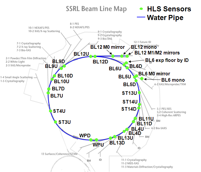
Reduced water level measurementsFor a better visualization of the results the value of sensor 'BL12-2 upstream' is subtracted from all other observations. In the graph below only one curve is depicted per insertion device (mean of the two sensors). A graph with the pitches of all insertion devices, providing information about the relationship of the sensors at each ID, is shown in the section below. The data presented here are filtered mean values for 2 min periods. Reduced water level measurements - AnimationThe floor movements during the last 48h are visualized here. In order to start the animation of the floor movement check the automatic box below. All graphs are with respect to the reference measurement at the East Pit and the time epoch 48h ago. Pitch of Insertion DevicesThe pitch is calculated as (downstream height - upstream height )/distance between the sensors. The data presented here are filtered mean values for 2 min periods. Beamline 12-2BL12 has 5 sensors installed along the beam. For a better visualization they are grouped together in one graph. Beamline 6BL6 has 3 sensors installed along the beam. |