SPEAR3 HLS Sensors from ID6 to ID4Contents
Related Documents
Location of the HLS sensors in SPEAR3To detect a tilt of the insertion device (ID) 6, one sensors has been placed on each end of the support structure along the beam, see Figure below. To look at the floor movement along the path of beam line 6 an HLS sensor has been installed close to the mirror. Further down the ring one HLS sensors has been installed on both sides of ID 4 on the floor. All the sensors are connected to each other to detect relative floor movements. The presented data are filtered to eliminate noise caused by bumps on the pipes or the HLS sensors themselves. The filter applied eliminates data if they change more than 5 µm in 2 sec. 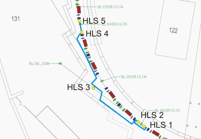
Reduced water level measurementsFor a better visualization of the results the values of sensor 3 are subtracted from all the observations. All dataThe data presented here are filtered mean values for 15 min periods. 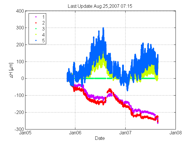
The movements at the sensor position seem to be correlated with precipitation, the data shown here are extracted from www.wunderground.com. 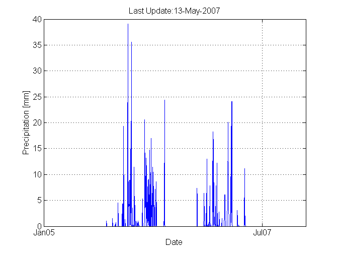
Last 24hFiltered data with a sampling rate of 2 seconds. 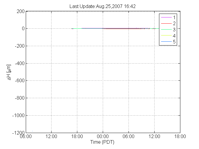
Pitch of ID 4The pitch is calculated as (HLS4-HLS5)/2.45 m. All dataThe data presented here are filtered mean values for 15 min periods. 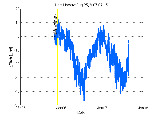
Last 24hFiltered data with a sampling rate of 2 seconds. 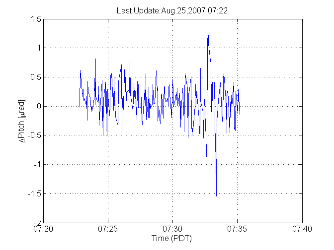
Pitch of ID 6The pitch is calculated as (HLS1-HLS2)/2.08 m. All dataThe data presented here are filtered mean values for 15 min periods. 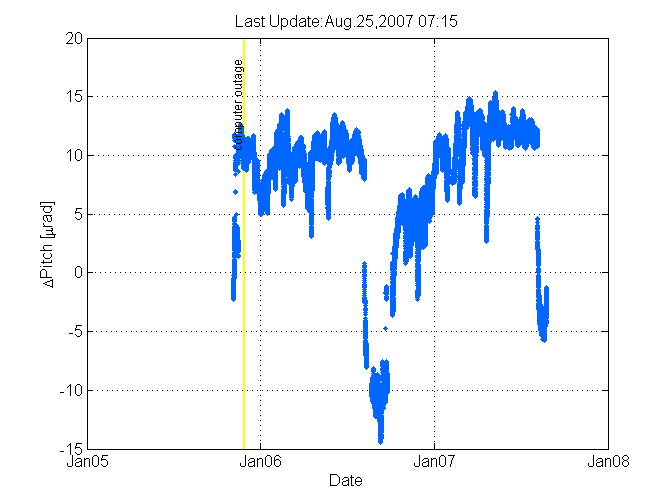
Last 24hFiltered data with a sampling rate of 2 seconds. 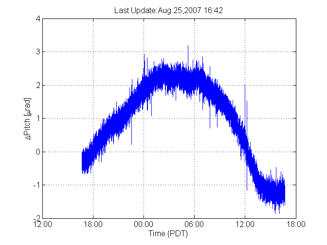
General InformationWater level: 6187 µm Temperature at
|