PROPOSED MECHANICAL DESIGNS FOR IMPROVED HIGH-SPEED IGBT PERFORMANCE
Presented here are several IGBT design approaches for
6,5ooV, 3,oooA pulsed service, with periodic dI/dt conditions of up to 15,ooo
A/uS. The die substrates are made of either Aluminum Nitride or FR4.
The heat spreader plate is an Aluminum-Silicon-Carbide matrix.
|
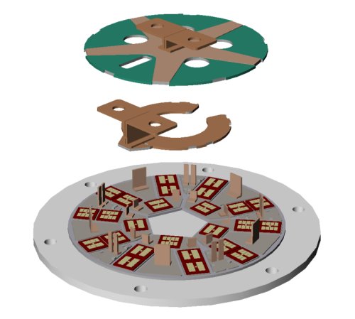
This first design is a radial adaptation of the basic Mfr 'A' layout, with equalized emitter bond wire lengths and a 'C' shaped circumferential collector busbar. The main emitter and collector busbars connect to the outside world at a single summation point.
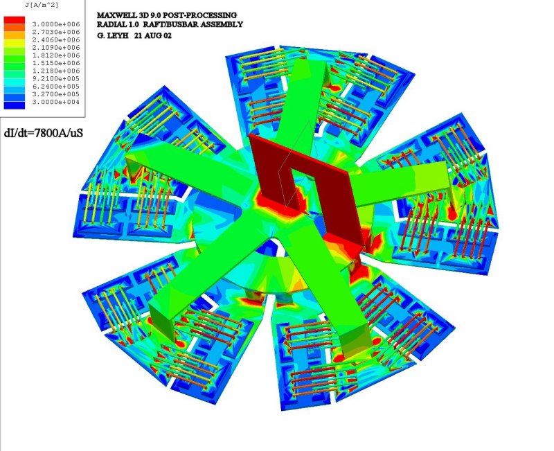
The current density performance of this design is shown below.
This first design suffers a number of undesirable current density variations, due to several effects.
Even though the bonding wires are the same length, they all exit a given die on one side, causing the outer-most bond wires to inductively shield the inner wires from the fast dI/dt currents. This can be seen in the alternating 'hot-cold' appearance of the bonding wires.
Another problem stems from the fact that the current in the collector busbar is not the same at all points, and consequently it couples varying amounts of current back into the nearby emitter bonding wires. The bonding wires on right side of the package nearest the collector terminal bear significantly more current than those on the left side.
 |
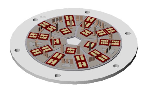 |
This next design attempts to address the problems encountered above, through several design changes:
1] The bonding wires now leave the die symmetrically to opposite sides.
2] The current flow pattern in the collector busbar has
improved radial symmetry, and the busbar is further from the bonding wires.
3] The main collector connection is closer to the central axis.
4] The emitter busbar is placed under the collector instead of above it.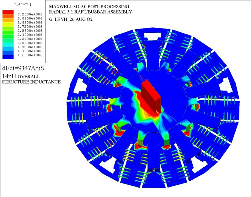 |
The current density spread for this design is now well within a factor of two. A slight asymmetry in the emitter wire currents still exists across the package, due to the asymmetry in the collector busbar current as it flows around the emitter terminal in the center. Offsetting the collector and emitter main terminals a small distance from the hot spot should cancel this remaining imbalance to first order.
The total IGBT package inductance has dropped significantly as well, to approximately one-half of the standard Mfr 'A' or 'B' packages.
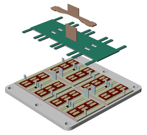 |
Although not radially symmetric, a rectilinear design offers
several advantages.
This design attempts to match the geometry of
the existing Mfr 'A' and 'B' technologies as closely as possible, in order to
maximize the possibility of having it seriously considered as a production
variant. Providing the same IGBT footprint also allows retrofitting of the existing modulator, with
minimal artwork changes to the PC board.
In this design the emitter busbar relies on its short aspect ratio instead of radial symmetry to equalize the emitter voltage drops from all the raft connection points.
The 8 die positions closest to the center are for the
anti-parallel diodes, but could also accommodate extra IGBT dies.
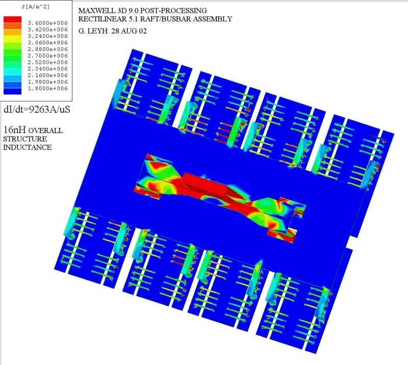 |
The performance of the rectilinear design is comparable to the radial design in overall current symmetry, but it exhibits slightly more overall inductance. This is due in large part to the fact that the rectilinear design has only 16 IGBT dies, where the radial design has 20 dies. Despite the small compromise in design symmetry, this approach may offer the greatest potential for a practical solution.
The next step is to develop actual working prototypes for both the radial and rectilinear designs. The development of both designs will proceed in parallel.
A custom manufacturer [Mfr 'C'] is presently working with SLAC to provide die placement and wire-bonding services.
Preliminary prototypes and performance data can be seen here.