This document describes the hardware and software architecture of the existing SLC Control System (SLCCS). Some attempt will also be made to reveal its evolutionary history to give a feel for what might happen to the NLC control system over two decades time.
Development of the existing SLC control
system was started in 1980 and has continued until the present day. Many
new functions and capabilities have been added to the SLC Control System
over the years but this document will concentrate on overall architecture
and not functional details. That is left for other documents in this series.
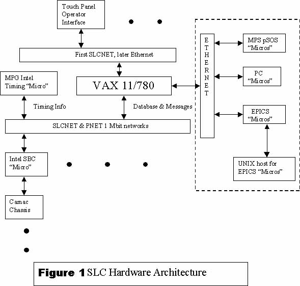
The SLC hardware architecture is shown in Figure 1 below with newer additions in the dashed area. There was initially a central VAX 11/780 connected via a home-grown network to 50+ single board Intel 8086 computers (SBC) in Multibus I chassis which are distributed around the accelerator. Each SBC received timing information from a single dedicated SBC called the MPG for Master Pattern Generator. Each SBC also had a two-way exchange of database information and messages from the central VAX and communicated with local CAMAC modules via a local serial interface. The two separate networks for general messages and database (SLCNET) and the timing information (PNET or Pattern Network) were different frequencies on the same CATV cable.
The primary operator interface was a dual
set of CRT screens shown in Figure 2. One screen
showed a touch panel control display by which an operator specified functions
to perform. Each panel was a matrix of 8 X 8 buttons which when pressed
performed some function. Some buttons called up other panels so the number
of possible total functions was unlimited. The other screen could show
plots or lists of items in response to requests from the touch panel. The
H/W interface between the VAX and the touch panel displays was originally
a specialized "micro" which communicated via SLCNET with the VAX. These
micros were fixed in the control room. There was also a terminal interface
which allowed one to access these panels from any terminal connected to
the central VAX though with reduced graphics capability.
Figure 2 SLC Touch Panel
and Graphic Windows
While the CPUs have gotten much faster and memory capacity has increased dramatically, the only major architectural change has been the support of Ethernet shown in the dashed area in Figure 1. Support for this standard network protocol allowed interaction with other types of "micros" and the running of a SCP on any computer that supported X-Windows.
The main and development VMS machines are now multiple Alpha processors instead of VAX processors with 2.5 Gbytes of physical memory and untold Gbytes of disk space but they still run a version of VMS that would be largely recognizable to the initial developers.
The Intel micro processors now top out at 100 MHz 486s instead of 5 MHz 8086s and memory capacity can go to 64 Mbytes up from the initial 1 Mbyte(?). The CAMAC interface has been redesigned to allow parallel operations and thus greater overall throughput. The Bitbus fieldbus is now used for some PEPII magnets instead of CAMAC. A special point-to-point network called Kisnet is used for direct inter micro communication in support of Fast Feedback.
In addition to the original Intel micros,
the SCP and main CPUs now also interface to VME SBCs running pSOS for the
Machine Protection System (MPS), EPICs displays for monitoring and control
of several new subsystems designed for PEPII plus various and sundry special
PCs for End Station runs.
The central VAX was the repository of all control system information. It contained a single executable called the Slc Control Program or SCP (pronounced skip) which contained all of the code to interact with the touch panels, the system database and micro communication.
Many instances of the SCP could be run, each of which was associated with a separate touch panel and its graphics display.
In addition to the SCP, some batch jobs were started when the control system was brought up (separate from VAX boot). These batch jobs performed background functions which were independent of any SCP. An example is a job called Paranoia which among many other things, performs a heartbeat function for all of the micros.
Into each micro was booted a single image
which contained the operating system (iRMX) and all application code. After
a micro was booted with this image, the database appropriate to it's devices
was downloaded.
The major evolution in the VMS application software has been the partitioning of the software into a hierarchy of sharable images. These are dynamically linked when a SCP is started and thus can be individually modified and released, subject to their defined dependencies.
With the arrival of EPICS, for the first time the VAX has been removed from the central part of the picture for these "micros" (IOCs) and replaced with UNIX systems for development and booting of all EPICS IOCs. The EPICs display tools now allow us to easily build graphic displays which under to old SLC system required a separate program for each display. With the implementation of a Channel Access server on the VAX control system which serves up much of the old control system database as EPICs Process Variables, we could use the EPICS tools to build any desired graphical display for existing SLC control system data.
On the Intel "micro" side we have gone through several versions of iRMX such that all micro code now runs in full 32 bit mode and the 64K segment limitation of the earlier Intel processors is no longer an issue. However, we still link an entire image which is downloaded and debugged in situ like always. The debugger is fully multitasking and now recognizes normal "C" syntax but again, architecturally is essentially the same as in the 1980s.
A significant attempt was made to replace
SLCNET with Ethernet for all of the Control System communications but this
proved much more difficult than anticipated for a variety of reasons.
The operating environment of the Control System Hardware includes the entire scope of the machine. Central computers can reside in a well controlled air-conditioned environment. Some computational power however must be distributed throughout the machine, spanning a distance of many miles and in more computer hostile locations.
The environment for the Control System Software is
one of constant change and enhancement by a substantial team of programmers
and Physicists.
It's hard to know what to say about the functional requirements of a H/W and S/W architecture but here goes.
- One of the main requirements for a H/W and S/W architecture is that for a long lifetime control system like the SLCCS it must ENDURE. It must be upgradable and maintainable over a long period of time.
- The S/W architecture must allow for nearly continuous change and upgrades by a locally distributed S/W team.
- The S/W architecture must be able to evolve with new technologies.
- The H/W architecture must be able to track the changes in computer evolution over a period of 20+ years.
- The H/W architecture must be implemented with cost-effective hardware at any given time period.
The performance characteristics of both the main VMS machines and the distributed "micros" are both about 100 times that of the initial system in terms of CPU performance and memory capacity of all kinds. The only constancy has been the SLCNET network.
I guess it's a truism that no matter what
the given performance of a system, more will always be desired.
The performance of the overall architecture
is of course dependent on all of its pieces and subject to the "weakest
link" problem.