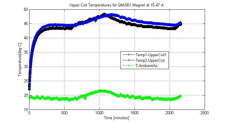
Temperature Behaviour of the QM-001 Quadrupole Magnet (Everson Tesla Quad)

                            Results from 36 hours at 15.47 A / ~ 2.5T


                  Achim W. Weidemann          -----------------      News of 06 Jan 2006 (updated 16:50)

Introduction

I now have run this magnet at 15.47A ( for a field of ~2.5T)for 36 hours
continually and measured its temperature throughout.
The results are shown below.

Temperature Sensor 1 ('Temp1') was affixed in the middle of the top surface
of the top coil closest to the connectors, Sensor 2 ('Temp2') in the middle
on the outside of the other top coil.  A third sensor was lying on the measurement table to
measure the ambient air temperature.
Temperatures were read about 3 times every minute.


Coil-Surface Temperature


Figure 0 above shows a the raw temperature data; one sees that the magnet temperature follows the ambient
temperature; it was started at 21:23 in the evening, so the peak at ~ 1000 minutes is ~ 1 p.m.

Fits to Coil Surface Temperatures

The Temperature vs Time curves were fitted to a function of the form:
      T_init + alpha*(1  - exp(-beta*t ), form, where T_init is the first temperature measurement.
using MathLab [3] From these fits, one can deduce the asymptotic outside temperature,
      T_asym = alpha+ T_init,
and a time constant,      
       timec = 1 / beta.
The figures below shows such fits and the residuals (data-fit); the top row shows the actually measured temperature,
for Sensors 1(left) and 2(right), the bottom 2 plots the fit to (measured temperature minus ambient temperature).

(Right-click on a figure and 'Open Link in New Tab' for a clearer view of any figure)
Fit to Coil-Surface Temperature
(r58: Temp1)
Fit to Coil-Surface Temperature
(r58: Temp2)
Fit to Coil-Surface Temperature
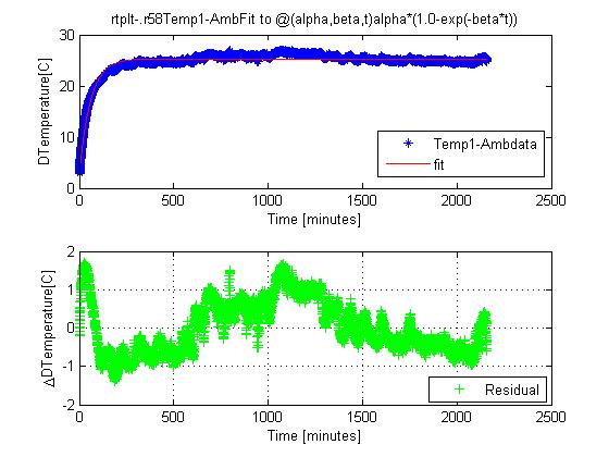
(r58: Temp1-Ambient)
Fit to Coil-Surface Temperature
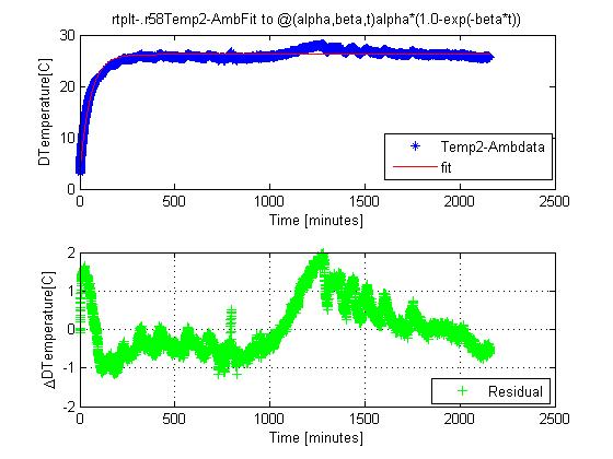
(r58: Temp2-Ambient)

One can clearly see the effect of the diurnal variation, the residuals still existing indicate an apparent delay
between ambient and magnet surface temperature.
The fit results are summarized in the following table which is an augmentation of the one previously given:

Datafile (rtplt...)
Sensor
r21
S1
r21
S2
r27
Sensor1
r27
Sensor2
r33
Sensor1
r33
Sensor2
   r58
Sensor1
  r58
Sensor2
r32
S1
r32
S2
Int. Strength  [T]
   3
2.5
2.0
Current  [A]
20.59
15.47
12.2
Lenght of measurement [h]
4
4
8
36
6
Ambient Temperature at end [deg C]
  20.6
22.7
24.6
19.8
23.8
Last measured Temperature [deg C]
61.8
64.6
48.5
48.5
50.2
50.3
44.5
45.4
41.0
40.9
 Asympt. Temperature [deg C]
60.8
64.4
   47.8
48.1
49.9
49.8
44.8
45.6
40.7
40.7
Time Constant [minutes]
51.2
57.8
   53.6
53.3
62.2
60.4
63.0
58.1
68.6
66.7
 Asympt Temp. above
 ambient[deg C]

40.3
43.6
25.2
25.5
25.6
25.5
25.3
26.2
16.7
16.6


The last row shows the parameter ('alpha'+T_init) derived from the fit to
 (Measured Temperature - Ambient Temperature).
I would consider that to be the best measure of the expected temperature rise above ambient.

Resistance Temperature Study

The calculation of the 'hottest' mid-coil temperature  was performed throughout the measurement, and
again lead to values below the measured surface temperatures.
Following a suggestion by Tanabe and Carr[4], I estimated the difference between surface and center
temperature as follows:
Assume   all input power P=IV to be generated in the center plane of coil
          P= dQ/dt = -k A dT/dx  with  k=0.8*0.391W/m-K =332 W/m-K (80% of copper value)
               
         dT/dx = (T_hot - T_surface)/(half-thickness of coil)              (half-thickness of coil=7.5cm/2)
         A = 4(coils)*(2*10.65*12 +2* 10.65*7.5+2*7.5*12) cm^2 = 0.238 m^2
         
        T_hot - T_surface = P *0.0375m/(332 W/m-K * 0.238 m^2) = P * 0.474 10^-3 K

       For Currents of (20.59, 15.47,12.2 A)  for the (3, 2.5, 2 T fields) one has V= (10.3, 7.4, 5.6 V)
       and resulting     T_hot - T_surface = 0.1, 0.05, 0.03 deg K.
So it seems that the expected difference between surface and center temperature is small.

To apply the  resistance-temperature formula [2]   I also checked the resistance of the magnet
with  Keithley 580 Microohmmeter, and found a value consistent with that reported by the measurement
program (which records voltage, current continuously).
I also  tried several different locations on the coil surface to find a presumably 'cooler'
spot  with a lower Temperature T_lowest   (which affects the outcome greatly, as it is
     T_hottest = 2*(AveTemp from  resistance) -T_ lowest)
both by moving the Sensor 2 around, and by a hand-held laser reflection thermometer, and
found variations of  a degree or less on the surface.

So I concluded that the estimate giving rise to the resistance-temperature formula in [2] is not
applicable to this magnet where the difference between inside and surface temperature is small.

References

1. Charge (R. Carr e-mail of Nov. 21, 2005)
2. Cherrill Spencer, SLAC's Magnet Coil Cooling Requirements for Air Cooled Coils. Memo of 20 Dec 2005 [MS-Word .doc]
3. MathLab code for generating the above fits and figures: rtanalysis2.m fitnplot.m fitalpha.m
4. E-mail from Roger Carr of 03 Jan 2006