
| Measured Int.
Field [T]: |
3.0075 |
2.504 |
2.0005 |
| Measured
Current [A]: |
20.591 |
15.475 |
12.20 |
| RT Data Sets |
.r21 (4h) |
.r27(4h),r33(8h) |
.r32(6h) |
 (r21: 4h,3T) |
 (r27: 4h, 2.5 T) |
 (r32: 6h, 2T) |
 (r33: 8h, 2.5T) |
| Datafile (rtplt...) |
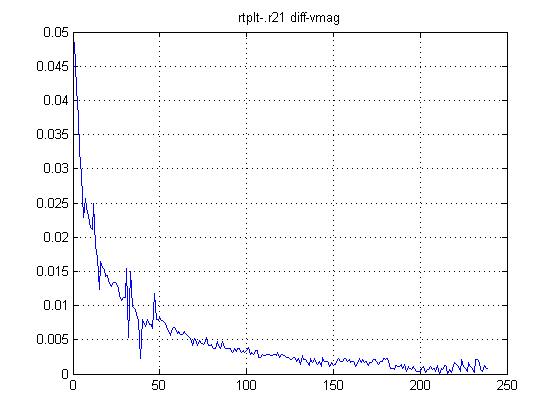
r21 |
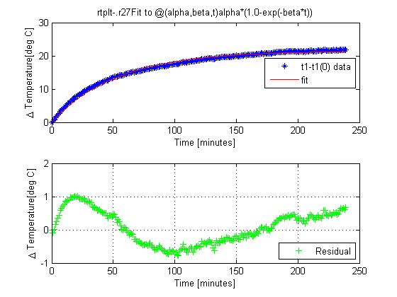
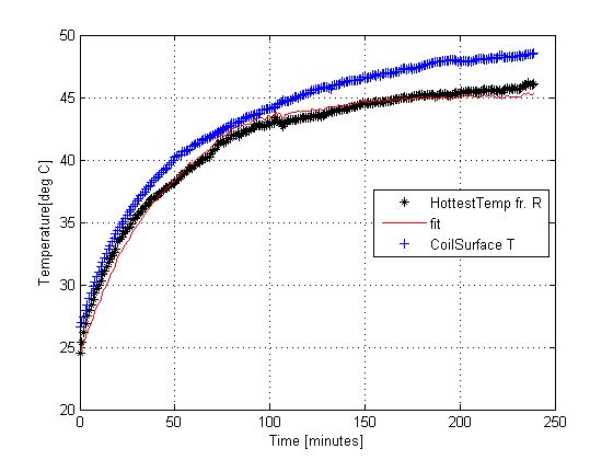
r27 |
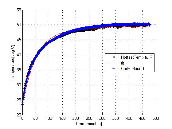
r33 |
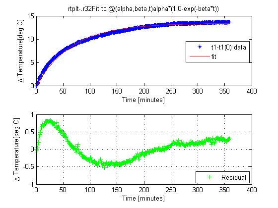
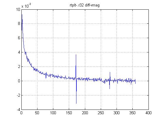
r32 |
| Int.
Strength [T] |
3 |
2.5 |
2.5 |
2.0 |
| Current
[A] |
20.59 |
15.47 |
15.47 |
12.20 |
| Lenght of
measurement [h] |
4 |
4 |
8 |
6 |
| Ambient
Temperature at end [deg C] |
20.56 |
22.67 |
24.58 |
23.79 |
| Last measured
Temperature [deg C] |
64.6 |
48.5 |
50.3 |
40.9 |
| Asympt.
Temperature [deg C] |
64.4 |
48.1 |
49.8 |
40.7 |
| Time Constant
[minutes] |
57.5 |
53.3 |
60.4 |
66.7 |
| Datafile (rtplt...) |
r21 |
r27 |
r33 |
r32 |
| Int.
Strength [T] |
3 |
2.5 |
2.5 |
2.0 |
| Current
[A] |
20.59 |
15.47 |
15.47 |
12.20 |
| Lenght
of measurement [h] |
4 |
4 |
8 |
6 |
| Ambient
Temperature at end [deg C] |
20.56 |
22.67 |
24.58 |
23.79 |
| Last
measured Temperature [deg C] |
64.6 |
48.5 |
50.3 |
40.9 |
| Asympt.
Temperature [deg C] |
64.4 |
48.1 |
49.8 |
40.7 |
| T_ave
[deg C] |
58.7 |
46.1 |
50.1 |
40.1 |
| T_Hottest
[deg C] |
52.6 |
43.7 |
49.8 |
39.4 |
 (r21: 4h,3T) |
 (r27: 4h, 2.5 T) |
 (r32: 6h, 2T) |
 (r33: 8h, 2.5T) |
 (r21: 4h,3T) |
 (r27: 4h, 2.5 T) |
 (r32: 6h, 2T) |
 (r33: 8h, 2.5T) |