5 July 2006
Stray Magnetic Fields Generated by Ion Pumps
Achim Weidemann
Magnetic Measurements, SLAC
Introduction
Ion pumps contain magnetic elements to shape the electric discharge responsible for the pumping action. As such pumps are installed in parts of the LCLS injector, where the beam energy is still small, stray magnetic fields near the beam orbit might be of concern, if large enough. Some 40 l/s Varian ion pumps [2] will be installed at a location which is about 13 inch above and about 13 inch sideways away from the beam, so one might assume that any fields are reasonably small at that distance. Nevertheless we decided to measure such stray fields in several configurations, and found that the magnetic field or its maximal transverse component is at most of the order of 0.25 Gauss at the beam location. We also compared two such pumps, and found their fields, at a closer distance, to differ by less than the measurement error.
Measurement Setup
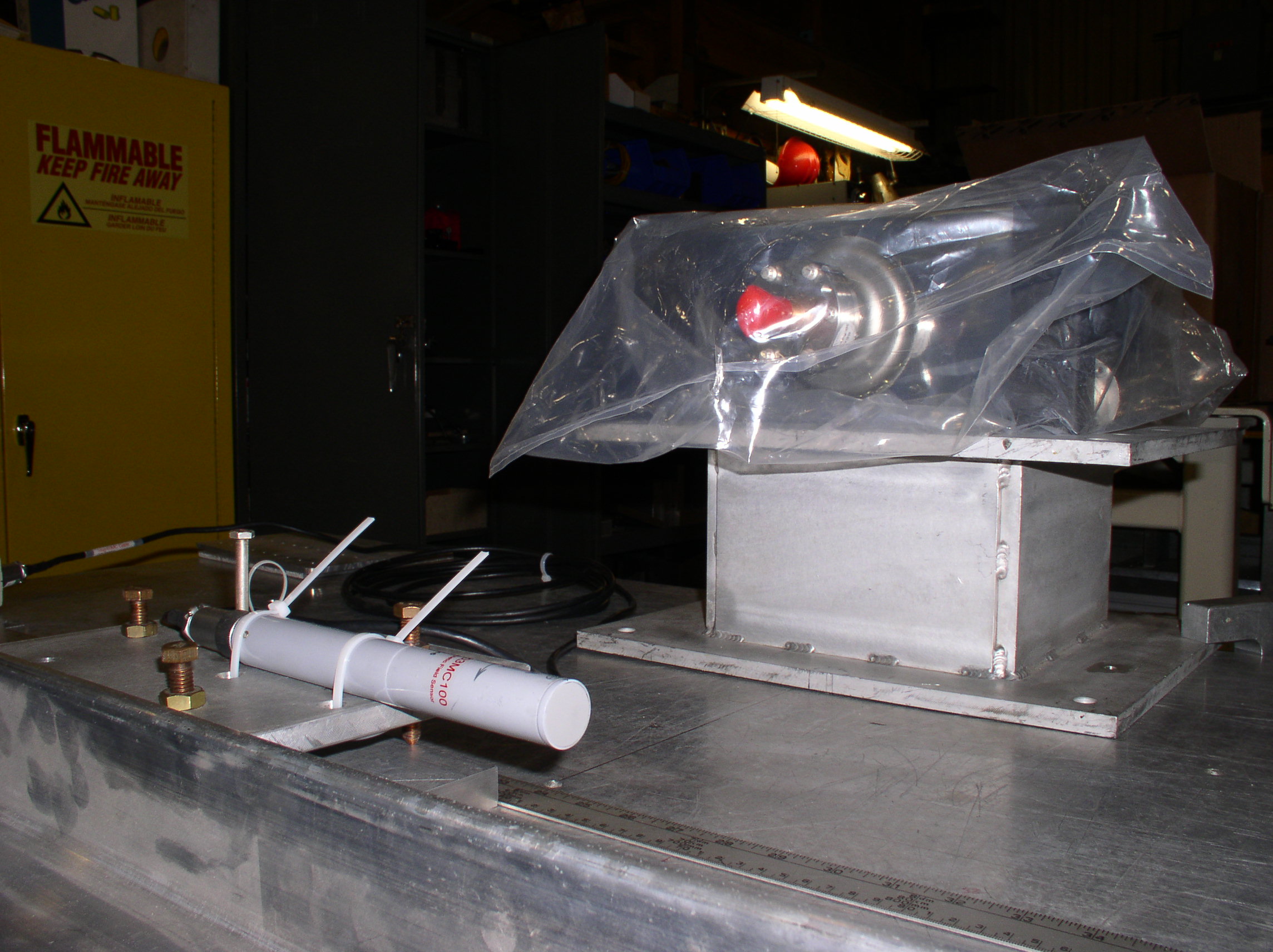
The magnetic fields were measured using a Bartington three-axis magnetic field sensor[1].
The cylindrical sensor was set up on a small Aluminum stage on an Aluminum table, so it could slide along a rail for a distance of 1 meter.
Figure 1. Measurement Setup: Here the pump sits on a stand, elevating its flange
center (`red snout') about 6 1/8 inch above the plane of the probe.
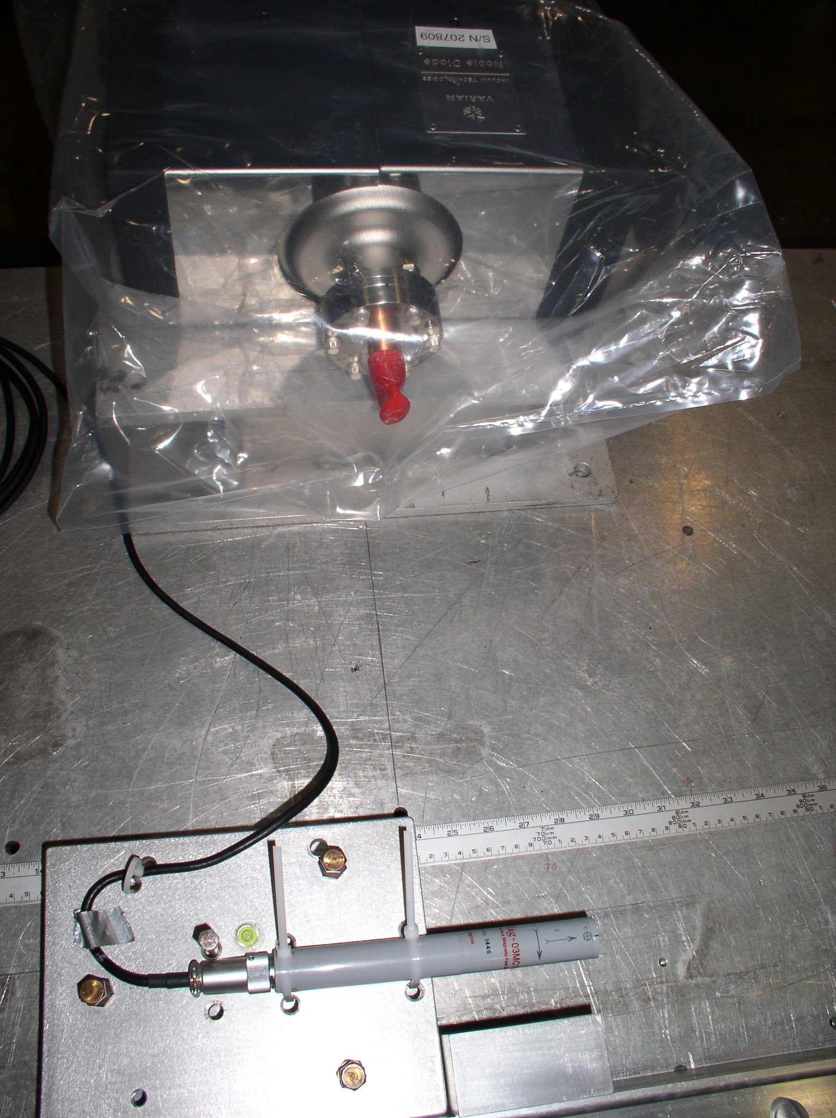
Figure 2. Measurement Setup - View from Top: The cylindrical probe measures three
components of the magnetic field, z: along axis of probe to the right, x: away from pump,
y: down. The distance in x between the surface of the flange (behind the red snout) and
the center of the probe is 13 inch.
The pump, a VacIon Plus 40 Ion Pump[2], was set on a stand and Aluminum shims, so that the center of the flange (with a red snout in figures above) was at a set distance (about 6 ¼ in or 13 in)
above the probe center, with the flange surface parallel to the z-direction of the probe, and the direction normal and away from the flange in the direction of the x-direction of the probe.
The surface of the flange was 13 inch away in x (horizontally) from the probe center.
The distance d shown in figures below increases from left to right in Figures 1 and 2, with d=50 cm
corresponding to the probe head being in line with the center of the pump flange.
Results
3.1 Background (Earth Magnetic) Field
The first measurement taken was one of the earth magnet field on the measurement table, without the pump (or similar magnetic material; indeed I identified a piece of unistrut below the table from a preliminary measurement and removed it!). The result is shown in Figure 3 below.
The x-component of the field ranges from -0.2 to -0.18 Gauss, the y-component from 0.32 to 0.39 Gauss, and the z-component from -0.098 to -0.185 Gauss; the absolute value from 0.39 to 0.47 Gauss.
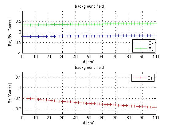
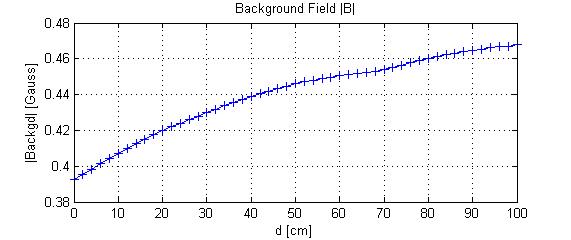
Figure 3. Background (earth magnetic) field on the measurement table.
(top: x,y-components, middle z-component, bottom: absolute value of B)
3.2 `6 1/8 inch above, and 13 inch sideways' position
The first set of measurements had the pump in the arrangement shown in Fig 1 above, with the snout of the pump about 6 1/8 inch above, and the pump flange surface 13 inch sideways from the center of the probe. (So this is closer than the `13 inch above, 13 inch sideways' position at which the pump will be installed; data for that are shown in section 3.3 below.)
Figure 4 below shows the field for that geometry, the x- and y-components never exceed ±0.25 Gauss
nearest to the pump centerline, and the z-component changes direction there, not going above +0.1 Gauss or below -0.1 Gauss..
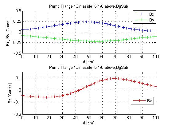
Figure 4A: Field components (background-subtracted) for the
'6 1/8 inch above, and 13 inch sideways' position
(top graph: x,y-components, bottom graph : z-component).
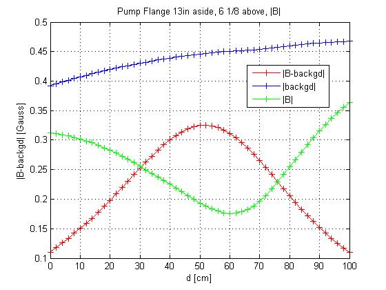
Figure 4B: Absolute value of
B-field for '6 1/8 inch above, and 13 inch sideways' position
[blue {top}curve: background field, green curve with minumum near 60cm : total B field,
including background, red curve peaking near 50cm: background-subtracted field].
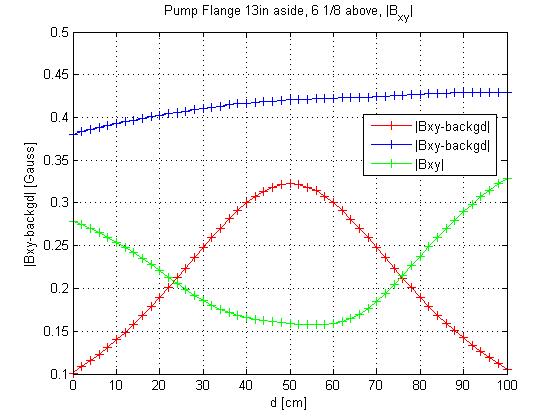
Figure 4C: Absolute
value of transverse B field ( (Bx2
+ By2 ) ½ ) for the '6 1/8
inch above,
and 13 inch sideways' position [blue {top}curve: background field, green curve: total B field,
including background, red curve peaking near 50cm: background-subtracted field).
3.3 `13 inch above 13 inch sideways' position
Most relevant is the configuration shown in Fig 5 below, with the snout of the pump 13 inch above, and 13 inch sideways from the center of the probe; the results for the field shown in Fig. 6.
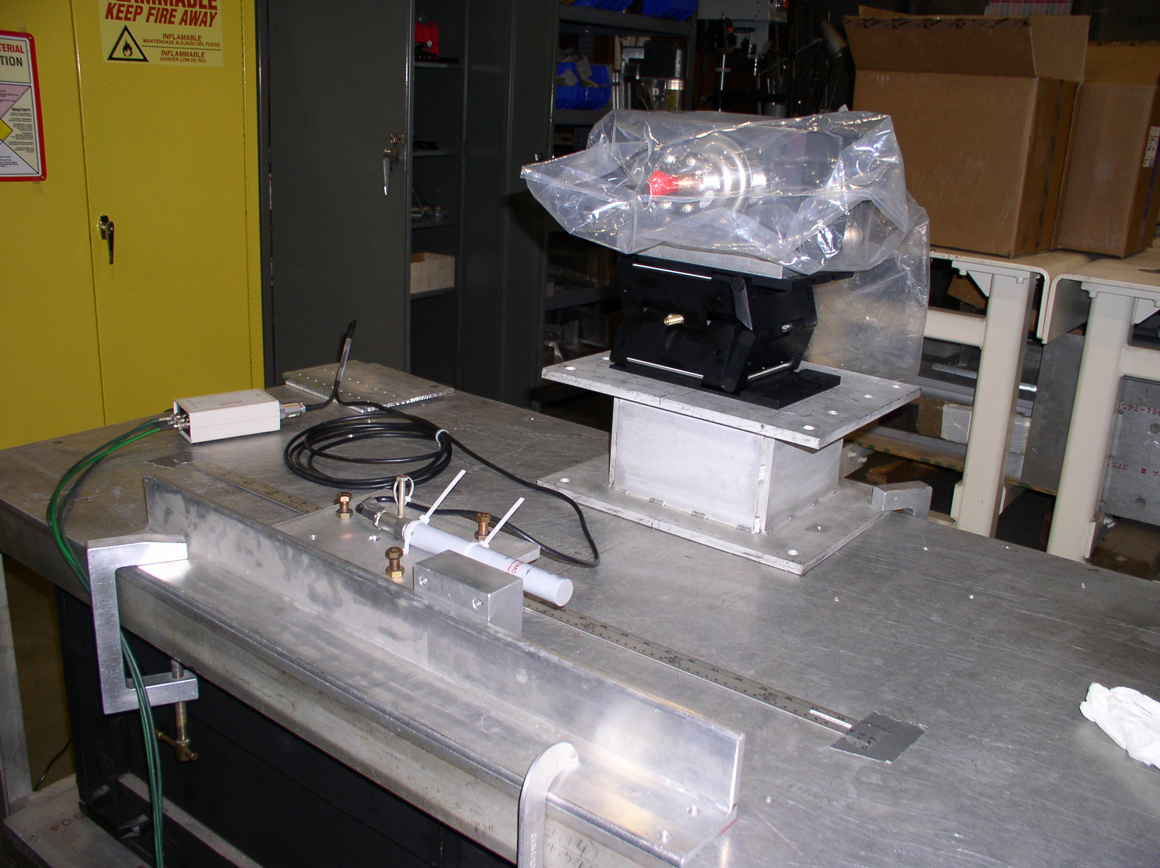
Figure 5. Measurement Setup for the `13 in above 13 in sideways' configuration.
Here the pump sits on an additional stand, elevating it 13 inch above the plane of the
probe center.
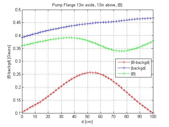
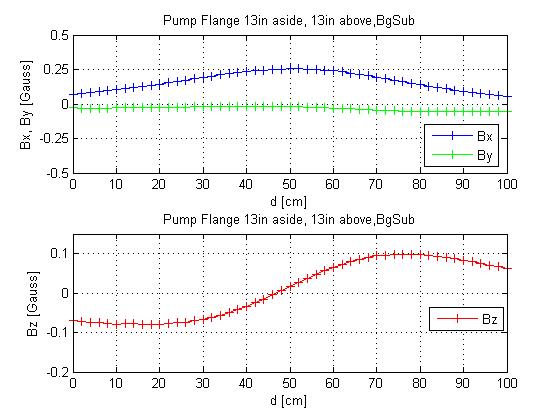
Figure 6A: Field components
(background-subtracted) for the '13 inch above,
13 inch sideways' position (top graph: x,y-components, bottom graph : z-component).
Figure 6B: Absolute value of B for the '13 inch above, and 13 inch sideways' position
[blue {top}curve: background field, green (middle)curve: total B field, including background,
red (bottom) curve peaking near 50cm: background-subtracted field).
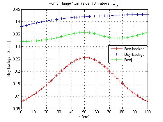
Figure 6C: Absolute
value of transverse B field (
(Bx2 +
By2 ) ½ ) for the '13 inch
above, and 13 inch
sideways' position [blue {top}curve: background field, green curve: total B field,
including background, red curve peaking near 50cm: background-subtracted field).
As expected, the maximal B-field nearest to the pump face is smaller for this position, about 0.26 Gauss, rather than 0.33 Gaus for the '6 1/8 inch above, and 13 inch sideways' position.
In the '13 inch above, and 13 inch sideways' position, the y-component (pointing down in the photograph of the setup) of the field is negligible, and the biggest component of the field, the
x-component (pointing away from pump) is at most 0.25 Gauss.
3.4 Pump mounted sideways -'Flip A' and `Flip B' position
Next, we considered mounting the pump with its shorter side 'parallel to the beam,'
or rather, the pump sitting on its shorter side, as shown in Fig. 7 below.
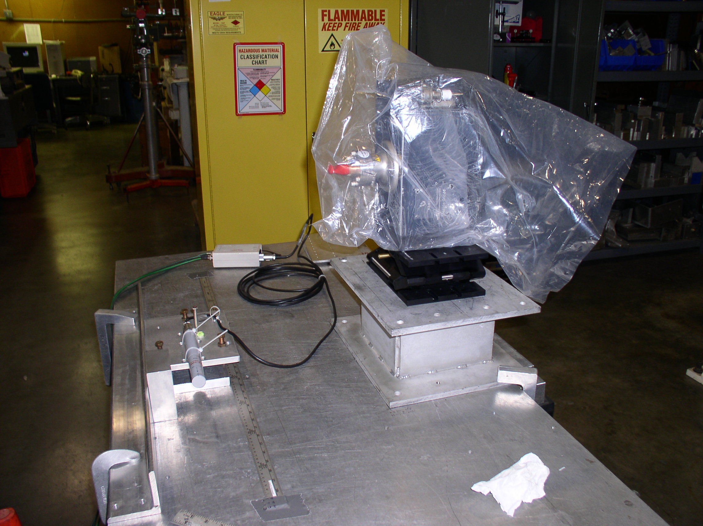
Figure 7. Measurement Setup for the 'Flip A' configuration, with the pump sitting on its
shorter side, and a connector on the top right. The stand is adjusted to elevate the flange
center (red snout) 13 inch above the plane of the probe center.
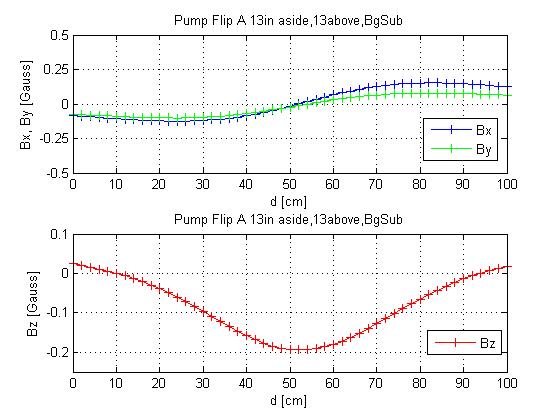
Figure 8A: Field components (background-subtracted) for the 'Flip A' position
(top graph: x,y-components, bottom graph : z-component).
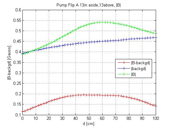
Figure 8B(previous page): Absolute value of B for the `Flip A' position
[blue curve: background field, green curve (top) with maximum near
60cm : total B field, including background, red curve (bottom):
background-subtracted field).
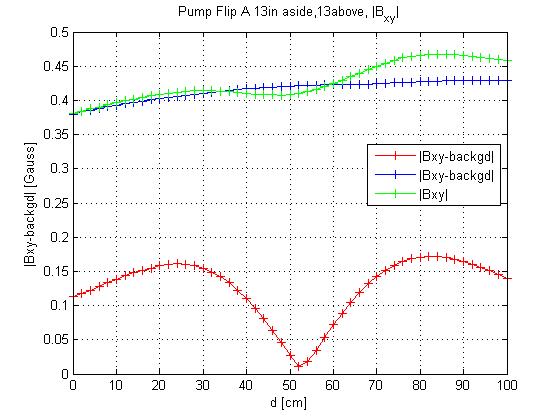
Figure 8C: Absolute value of transverse B field ( (Bx2 + By2 ) ½ ) for the 'Flip A ' position
[blue curve: background field, green curve: total B field, including background,
red (bottom)curve with minimum near 50cm: background-subtracted field].
To check the consistency of these measurements, we also turned the pump upside down, (`Flip B') so that it sits on that shorter side with a connector (which is barely visible behind the plastic, at upper right of pump in Fig.7). An additional shim, required to keep the puimp stable in this position, however elevated the flange center (red snout) 13 ¼ in above the plane of the probe center.
Comparing Figures 8 and 9, one sees that the components of the field change sign, appropriately.
In both `Flip A' and `Flip B' positions, the size of the x- and y-component of the field are small, of order 0.1 Gauss; in the original position (Figs. 5-6), Bx is as large as 0.25 Gauss, but By
is close to zero. Bz goes from about -0.1 to +0.1 Gauss in the original position, and peaks at about +/- 0.2 Gauss in the `Flip' position. The maximal absolute value of B is smaller in the `Flip' position, ~0.2 Gauss, than the ~0.25 Gauss in the original position.
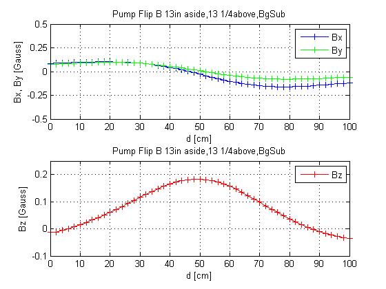
Figure 9A: Field components
(background-subtracted) for the 'Flip B' position
(top graph: x,y-components, bottom graph : z-component).
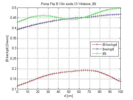
Figure 9B: Absolute value of B for the `Flip B' position
[blue curve: background field, green curve (top) total B field, including
background, red curve (bottom): background-subtracted field).
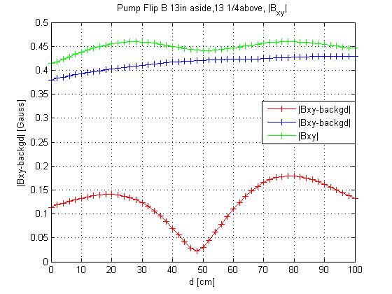
Figure 9C: Absolute value of transverse B field ( (Bx2 + By2 ) ½ ) for the 'Flip B ' position
[blue curve: background field, green curve: total B field, including background,
red (bottom)curve with minimum near 50cm: background-subtracted field].
Comparing Figures 6C, 8C, and 9C, one sees that, if the long side of the pump is parallel to the beam direction, the magnetic field transverse to the beam peaks at about 0.25 Gauss nearest to the pump;
if one mounts the pump sideways, with its short end parallel to the beam, the transverse field has two
maxima of less than 0.2 Gauss some 30 cm away from the pump along the beam (z) axis.
Integrating the background-subtracted transverse field (Bx2 + By2 ) ½ over the 51 data points (d=0 to 100 in 2cm-steps), the range shown in the figures, and ignoring the field further away, one obtains
for the `long side parallel to beam' position: 17.4 Gauss-cm
for the 'Flip A' position: 12.9 Gauss-cm,
for the 'Flip B' position: 12.7 Gauss-cm,
which might make one prefer one of the `Flip' positions. However, this ignores how fast the stray field decreases outside the region measured and shown in the plots.--
3.5 Different pump of same model
Finally to check if there are significant variations between different pumps, I also mounted another pump (`Pump2', S/N 207813), and measured its field in a position close to that of Fig.1 (`13in aside,'~ 6 ¼ in above'). The results are shown in the Figures 10 (to becompared with Figure 4) for the fields of Pump2, and Figures 11 and 12, which show the differences of field components and absolute value of the field.
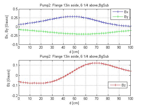
Figure 10A: Field components (background-subtracted) for the second pump
'6 1/4 inch above, and 13 inch sideways' position
(top graph: x,y-components, bottom graph : z-component).
As seen in Figures 11 and 12 below, the differences to the values shown for the other pump (`Pump 1') in Figures 4A and 4B is small, at most 0.05 Gauss for the field components, and 0.05 Gauss for the absolute value of the field, which is better than the measurement error, and most likely due to the difference in aligning the pump with respect to the (x-)axis perpendicular to the movement of the probe. This indicates that different pumps of this make and model do not have significantly different stray fields.
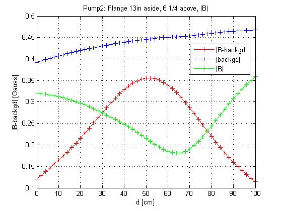
Figure 10B: Absolute value
of B-field for 'Pump2 6 1/4
inch above 13 inch sideways' position
[blue {top}curve: background field, green curve with minumum near 65cm : total B field,
including background, red curve peaking near 50cm: background-subtracted field).
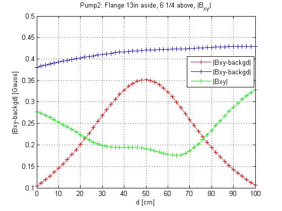
Figure 10C (previous page): Absolute value of transverse B field ( (Bx2 + By2 ) ½ ) for the
'Pump 2 6 1/8 inch above, and 13 inch sideways' position [blue {top}curve: background field,
green curve: total B field, including background,
red curve peaking near 50cm: background-subtracted field).
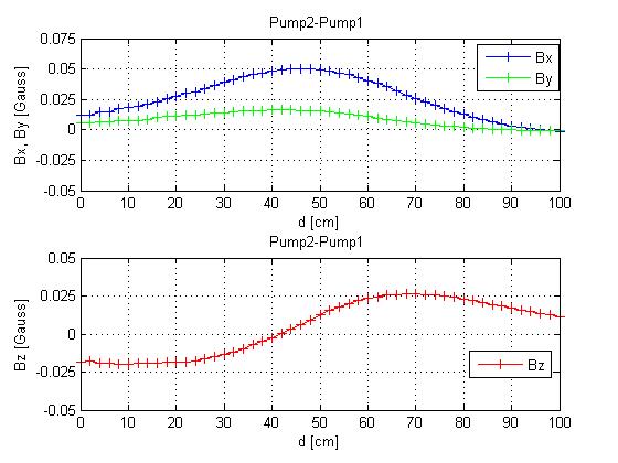
Figure 11. Differences of field components (Pump2 – Pump1)
(top graph: x,y-components, bottom graph : z-component).
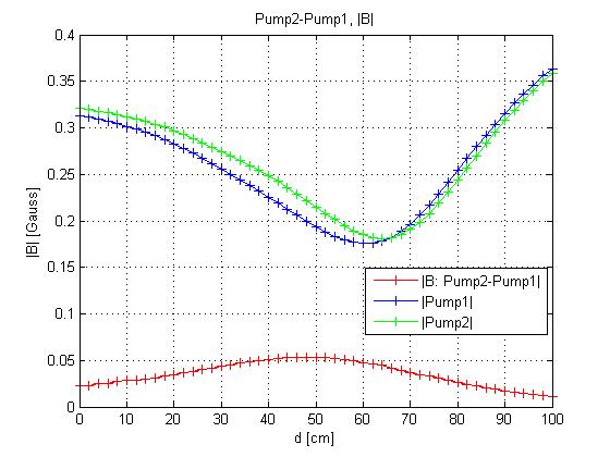
Figure 12. Absolute value of field: Green curve: Pump2, blue curve: Pump1,
red (bottom) curve: (Pump2 – Pump1). The offset between the gree and blue
curve indicates a possible pointing error.(difference in alignment of pump axes).
Endnotes & References
1.Bartington Mag-03 MC 100 Three-Axis Fluxgate Magnetometer S/N 1446, with a Mag-03M Power Supply Unit, S/N 856. This device provides 3 analog voltages proportional to the magnetic field, which were read out with a HP 3457A Multimeter.
This magnetometer agreed to 2% (at 2V =0.2 Gauss) with similar ones (Mag-03MC S/N 447 and 196, with Power Supplies S/N856 and S/N 0260) to 2.5% or better.
2.Varian VacIon Plus 40 Ion Pump P/N 9191220M001, S/N 207809 ; http://www.varianinc.com/cgi-bin/nav? products/vacuum/pumps /ion/vacion40/ index&cid= IQOMIIJJFL