Ion Pump Stray Field Study
Achim W. Weidemann last updated: 10-Feb-2006
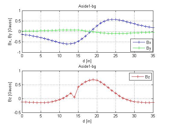
Below please find some plots from measurements of the stray fields of an ion pump. Of particular concern were fields at a distance of about 7.5 inch from a flange.
Hence I arranged a Bartington Mag03 MC 100 3-axis probe to slide along a straight line, with the probe center about 7.5 in from the flange surface, perpendicular to the flange.
Figure 1 above shows the 3 field components with the pump lying on its side (so that the labes are on top and bottom); the x-axis is away from the pump flange, y-axis up, and z-axis along the line of movement (parallel to flange, possibly parallel to beam line).(d increasing to right, when seen from pump; pump center just below 20 in)
The next figure 2 below shows the same, after some mu-metal shielding had been applied, and Fig.3 shows the difference (fields without shield– fields with shield).
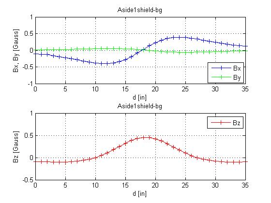
Fig.2
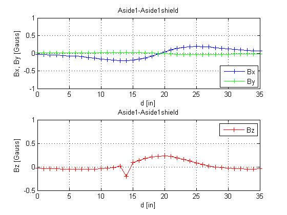
Fig 3
Then I flipped the pump over, so that the labels are on the sides, and repeated this measurements. (So z-axis -axis of movement/d is along what
was the y-axis above). A shim was applied to keep the pump center at
approximate pump center height.
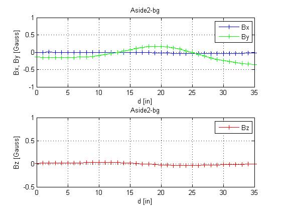
Fig.4
above shows that indeed the y-
and z- field components are as expected; Fig.5 below shows the same
with the shielding
applied,and Fig 6 the difference of the fields for the unshielded-shielded pump
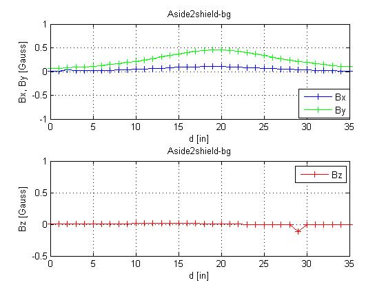
Fig. 5
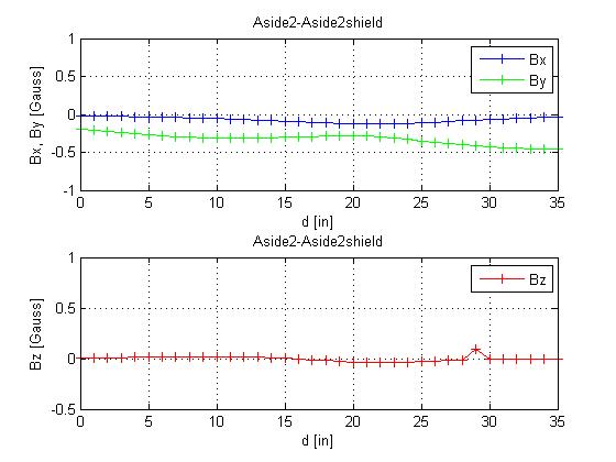
Fig. 6
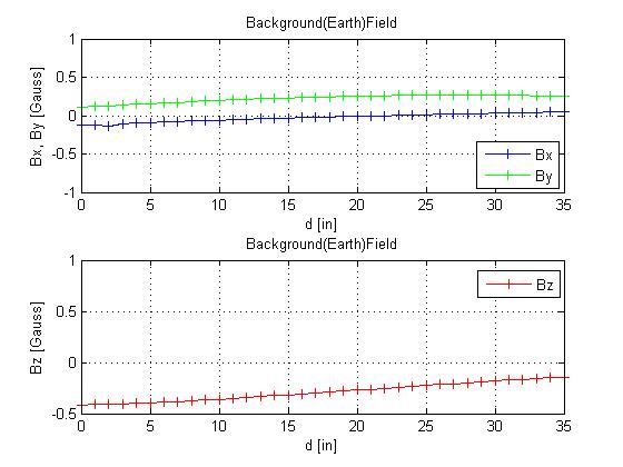
Figure 7 here shows the size of the background/ earth magnetic field
which was subtracted in Figs. 1,2, and 4,5.