
March 29, 2006
Switching Effects of OCEM Power Supplies
Briant Lam and Achim Weidemann
(Power Conversion & Magnetic Measurements, SLAC)
1. Introduction
A redundant power supply system is being considered for usein the ILC. This system consists of a bin containing 4 or 5 OCEM Power Supply cards (28V 50A each), of which at any time three are used to power a magnet. Should one of these three fail, the
system switches its load to the fourth one.
We investigated the effects of this switching and recovery on the output current and the magnetic field of a dipole magnet. We found a drop in output current of as much as 8A (from 120 A) and in magnetic field of about160 Gauss (from 2.5 kGauss). The return to full current and field takes more than 400 ms.
2. Setup and Measurement Procedure.
A test stand in the Power Conversion Lab has a bin with 4 OCEM cards powered by a Lambda EMI EMS 30V 165 A Power Supply. The output of this system delivers a current of 120 A to a dipole magnet labeled VB 571.A manual switch allows to induce the fault condition which makes the system switch to the redundant OCEM card, and also
can provide a trigger for an oscilloscope. The current could be observed on the oscilloscope.
To measure the magnetic field, a Hall Probe [1] was installed approximately in the center of the dipole magnet aperture in the middle of the magnet.
This probe was supplied with a 100mA current from a Hall Current source [2] .
The output of the probe was amplified with an amplifier [3](at 100x gain, a few kHz low-pass), and observed on an oscilloscope [4]
The Hall probe output in this arrangement was calibrated by comparison with a hand-held probe [5], using a permanent magnet (at ~4.7 kG), and also the field of the dipole (~2.5 kG at 120A); both agreed to a few tens of Gauss, which can be attibuted to a slight rotation of one probe compared to the other.--
3. Results
The switching of the power supply does lead to a reduction in voltage and current,
as shown in the Oscilloscope trace of Fig.1
Figure 1. Oscilloscope trace of current (top, blue trace; 3A/division) and voltage (bottom, green trace, 2.5V/division) .Time scale is 20 ms. Load was about 0.1 Ohm.
Here, with a load of about 0.1 Ohm, the voltage dropped by about 3.1V and the current by about 2.4 A (from 120 A), The voltage recovers in about 30 ms, the current in about 140 ms.
The same observation made with the dipole magnet and a load of about 50mOhm in series, is shown in Figure 2:
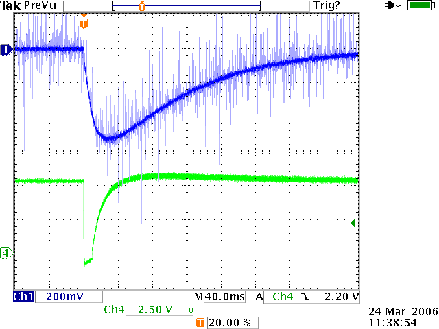
Figure 2. Oscilloscope trace of current (top, blue trace; 3A/division) and voltage (bottom, green trace, 2.5V/division) .Time scale is 40 ms. Load was about 0.05 Ohm
in series with dipole..
This time, the voltage drops by about 6.25 V from 12V, recovering in 40 ms (with perhaps a 350mV overshoot), and the current drop is 7.7 A, taking more than 320 ms
to recover.
Assuming that the current drop is exactly proportional to the drop in magnetic field,
we would expect the latter to be (7.7A/120A)*2.5kGauss ≈ 160 Gauss.
The following 3 Figures show Oscilloscope traces of the Hall Probe voltage. While there is much noise, the top trace can be discerned and shows evidence of the drop in magnetic field of about the expected magnitude.
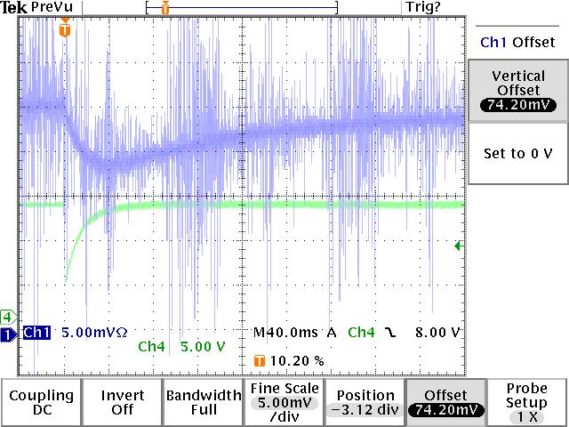
Figure 3. Trace of amplified Hall Probe Voltage (upper, blue trace, 5mV/division)
and voltage drop (bottom, green trace, 5V/division)
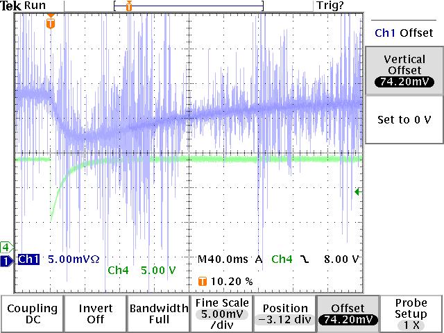
Figure 4. Trace of amplified Hall Probe Voltage (upper, blue trace, 5mV/division)
and voltage drop (bottom, green trace, 5V/division)
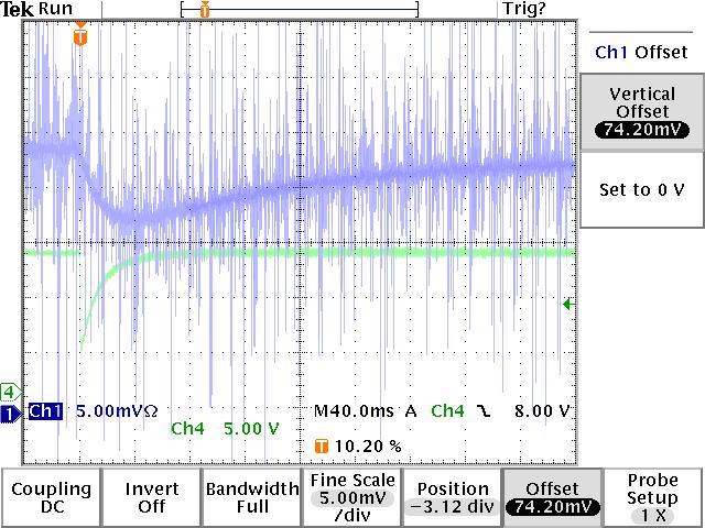
Figure 5. Trace of amplified Hall Probe Voltage (upper, blue trace, 5mV/division)
and voltage drop (bottom, green trace, 5V/division)
In the three figures 3-5, the Voltage drop observed is about 8.8V, and the drop in amplified Hall Voltage 6.43 mV, corresponding to about 160 Gauss [6] , exactly as expected from the current drop.
While the voltage recovers to its set value within 50ms, the current and field recover
much more slowly, and indeed do not reach the set value within the 400ms shown above, due to the large inductance of the dipole.
Endnotes
1. F.W. Bell Hall Probe.
2. Valhalla Scientific 2701C Programmable Precision DC Voltage/Current Standard.
3. Stanford Research Systems Model SR560 Low-Noise Preamplifier.
4. Tektronix TDS 3014B 'eScope'.
Lakeshore Cryotronic Model 410 Gaussmeter, S/N 41741, with Transverse Probe S/N
H02465 Cal. No. 968.
6. The change in Hall probe voltage when ramping the dipole from 0 to 120 Volt was
100mV; the hand-held probe measured 10 Gauss remnant field and 2.49 kG at
120A; thus the scale is 2480.G/100mV= 24.8 G/mV .(Calibration with the permanent
magnet at 4.7kG gave a slightly larger scale factor of 25.4 G/mV).
6.43mV* 24.8G/mV =159.5G , 6.43mV* 25.4G/mV =163.3 G.
Misreading the Oscilloscope trace by 0.5mV would add another 12.5G to the error.