Vertical Comparator for the Calibration of Leveling Equipment
The vertical comparator was built in 2003 in the SLAC Metrology laboratory which is situated in the old access tunnel to the linear accelerator below sector 10. Its walls are made of concrete and have a thickness of about 1m. The whole laboratory, except the portal, is beneath the surface, which gives the laboratory excellent thermal stability. Even though, the laboratory is air conditioned to achieve a constant temperature of 20°C, which is the accepted temperature when calibrating instruments any time of the year. The facility is designed to calibrate 3m long invar staffs, both for system calibration of digital levels and for traditional staff calibration. Digital levels have the advantage of delivering highly accurate and fast measurements in an automated measuring process. Their disadvantage is that they give less accurate measurements in some cases. To give an overview of the current and ongoing investigations a few examples are given: Scale Factor: To achive the highest accuracy with a level in combination with a rod, the determination of the scale factor is necessary.
Critical Distances: It is already well known in the metrology community that digital levels give inaccurate results at certain distances. Therefore the expansion of these distances have to be evaluated to avoid them during the field measurements. As an example, measurements at and around a critical distance of the DNA03 are shown below.
End Sections of the Staff: For the determination of the height reading, a certain area of the code on the leveling rod is used by the level. If only parts of this area are visible, as is the case at the end sections of the staff, inaccurate measurements are the consequence.
Illumination: Leveling instruments are passive measurement systems that use ambient light to read the rods. In tunnels, we use flashlights to illuminate the rods and allow measurements. Therefore tests with our instruments have to be carried out to find out if the inhomogeneous illumination of flashlights has an effect or not. By taking more then 100 measurements at a sighting distance of 3 m, illuminating the staff with a flashlight (Black & Decker Snake Light) in front of the rod and up to an angle of about 45°, either no measurements were taken or the measurements were correct. But taking measurements with the illumination at a very steep angle (see Picture below) deviations of up to 0.1 mm could be invoked. This can be explained by a shadowing effect of the code elements.
|
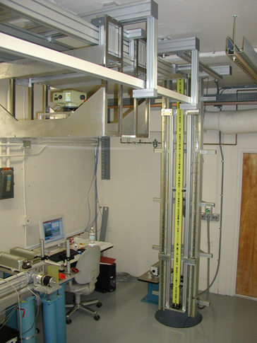 At SLAC a fully automated vertical comparator for
the calibration of digital levels and invar staffs was developed
by the Metrology Department in cooperation with the Institute
of Engineering Geodesy and Measurement Systems at the Graz University
of Technology.
At SLAC a fully automated vertical comparator for
the calibration of digital levels and invar staffs was developed
by the Metrology Department in cooperation with the Institute
of Engineering Geodesy and Measurement Systems at the Graz University
of Technology.